
Renderer Interface Overview
Lesson 1 of 3
Renderer GUI Structure
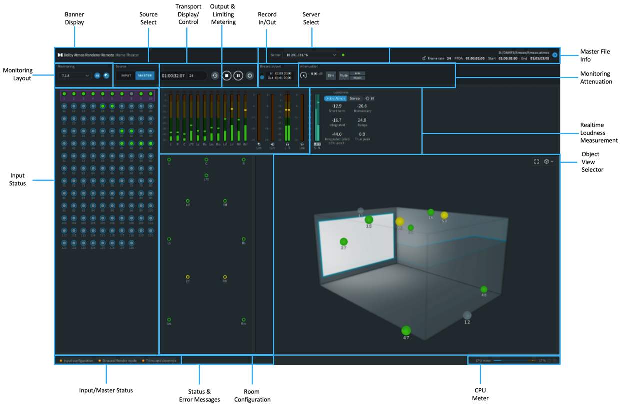
The top portion of the Renderer UI is where most operational actions take place. This area includes displays and controls for the software operation mode, master file, monitoring functions, transport controls, recording controls, and more.
The bottom portion of the UI provides visual displays of input status, room configuration, output and limiting meters, real-time loudness measurement, and the Object view.
Master File
The Master File section displays master file information and provides access to options for locking or unlocking a master file, and setting/changing the First Frame of Action.
The First Frame of Action (FFOA) is a common film term that denotes the first frame where visual content appears. This is typically at the one-hour timecode location (01:00:00:00) but may vary depending on the delivery specifications for different projects.
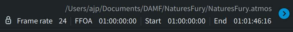
The primary master file information is displayed at all times in the Master File section and includes the following elements.
Click the markers (i) to familiarize yourself with the various parts of the Master File Information section.
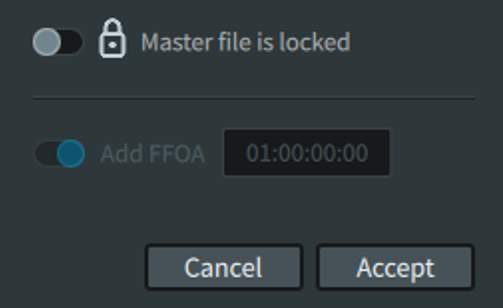
The master file reveal triangle opens the settings shown in the image, allowing you to make changes:
- The Master file lock switch toggles the master file between locked and unlocked states. When locked, the master file is read only. When unlocked, the master file is read/write. Place the switch in the locked position to enable read-only mode when listening back to a master, or to avoid writing over the master. Place the switch in the unlocked position to record to a master or perform a punch-in-and-out record. Only DAMF packages may be recorded to or edited; a .wav or .mxf file cannot be unlocked for editing.
- The Add FFOA option switch and display enables the FFOA metadata parameter (in hh:mm:ss:ff) so that it is available in the master file for reference in subsequent workflow steps such as encoding. When active, the field allows a new value to be entered. The field will display the FFOA for an open file for read-only playback or punch-in and punch-out recording. If the file is opened for a punch in/out recording, the value can be changed to rewrite the new value to the file. If the FFOA and in-point are the same, specifying the FFOA is optional per the delivery specification.
Monitoring Layout
The Monitoring layout beneath the Banner display on the left side of the header provides a drop-down menu for selecting the room layout, as well as indicators for sample rate and spatial coding emulation status (on/off).
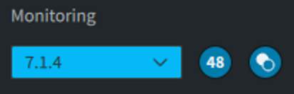
The drop-down menu allows the room layout (or room configuration) to be selected for monitoring purposes. Physical may be selected (which represents the physical layout of all speakers in the room, based on the speaker setup configured in the Room Setup window). Downmix monitoring layouts of 7.1, 5.1, 2.0 are also selectable.
Any custom layouts previously defined for the Renderer as a subset of the Physical layout (such as 5.1.4) will be displayed. The default layout is Physical. It is not possible to define a customer speaker layout larger than that of Physical layout.
The selected room layout is reflected in the Renderer window Room Configuration display and metering. The selected layout does not affect the recorded data when recording a new master.
To the right of the Monitoring drop-down menu is a sample rate indicator. This displays the sample rate in use by the Renderer (48 kHz or 96 kHz), as set in Driver preferences.
Next to the sample rate indicator is an icon that indicates whether spatial coding emulation is enabled or disabled. When enabled, the icon is blue and white, indicating that spatial coding emulation is being applied to monitoring outputs. When disabled, the icon is grayed out. Spatial coding emulation can be toggled on/off in Processing preferences.
Source Selection
The Source selection area provides buttons for selecting the listening mode: Input mode or Master mode.
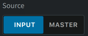
The Input button allows audio from the Renderer inputs to be listened to, including any processing configured in the Renderer. The Renderer is automatically in Input mode while live-monitoring a Dolby Atmos mix, recording a master, or actively recording between punch-in and punch-out points.
The Master button allows audio from the open master file to be listened to. The Renderer is automatically in Master mode after a master is opened, as well as when playing back outside of the punch-in and punch-out points during a punch recording.
When playing back a master, it is possible to toggle between Input and Master.
Transport Display and Control
The Transport section includes the timecode display and transport controls that are used for monitoring, playback, recording, and syncing to an external source.
Click the markers (i) to familiarize yourself with the various parts of the Transport Display and Control section.

Record In/Out
The Recording Controls section allows a predefined recording range to be set prior to recording.
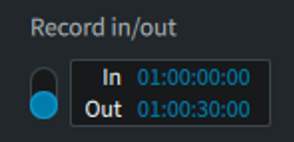
This section includes an On/Off switch that enables or disables the In and Out points for configuring a record range. When off, the In and Out points are grayed out.
The In-point defines the timecode location (in hh:mm:ss:ff) where recording will begin. The Out-point defines the timecode location where recording will end.
Monitor Attenuation
The Monitor Attenuation section provides controls for attenuating, dimming, or muting the monitor output of the Renderer, as well as controls for muting Beds only or Objects only.
Click the markers (i) to familiarize yourself with the various parts of the Monitor Attenuation section.
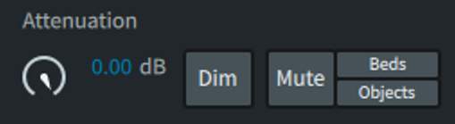
If using an external monitor controller be aware of the Renderer attenuation, dim, and mute settings to avoid conflicting or duplicate settings.
Input Status
This section shows all 128 Renderer inputs, with the inputs numbered for easy identification.
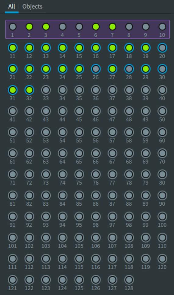
Each of the 128 input channels is represented by a circle, which provides signal and status information. Bed audio groups of inputs are surrounded by purple rectangles. For Beds and Objects, the color of the inner circle represents signal presence and level. The presence and/or color of a ring around an Object circle, or the rectangle around the Bed inputs, represents input status.
This image shows examples of status information displayed for different input channels.
Input Status Indicators
The input status indicators in the main window display Beds and Objects being rendered in the Dolby Atmos session during monitoring or recording, or when playing back a master. The indicators identify the role of the input channels (as Beds, Objects, or unassigned channels) and display the respective channel signals in real time.
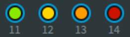
- Green: starting at –93 dB
- Yellow: starting at –20 dB
- Orange: starting at –6 dB
- Red: 0 dB
These color and level associations are also used in the Room Configuration, Metering, and Object View.
Input Channel Status Rings
The color of the ring around an input status circle represents the state of the associated metadata source.
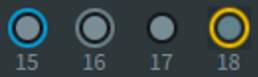
The status rings show colors (Teal, Gray, None, or Yellow) to indicate whether the input channel has an active metadata source connected. The ring color indicates status as follows:

- Teal ring (Objects only): An active metadata source is connected to the Object ID (for example, an Object panner in Pro Tools Ultimate).
- Gray ring (Objects only): The active metadata source is not assigned an input, but the input is designated as an Object. The Object is not used.
- No ring: The channel has no Bed or Object assigned to it (that is, the input is set to “–” in the Input Configuration window.)
- Yellow ring: Either an Object is defined but has no incoming metadata, or there is incoming metadata but the Object is not defined in the input.
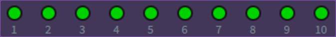
Purple Rectangle
Input channels shown within a purple rectangle are assigned as a Bed in the Renderer Input Configuration window (Window > Input Configuration).
Room Configuration
The Room Configuration in the main window provides a visual representation of Renderer output to speakers.
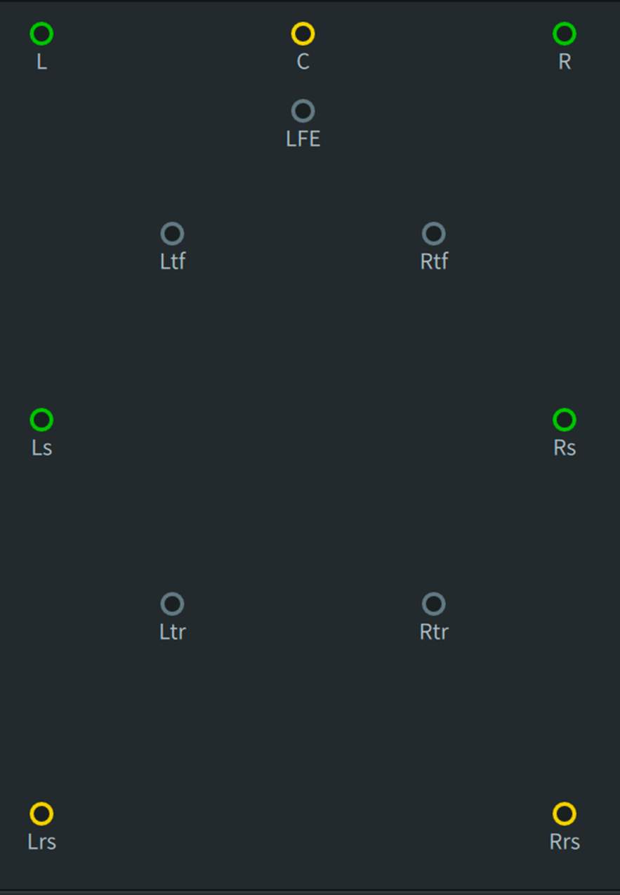
From this section, the output to any speaker can be muted or soloed by clicking or COMMAND+Clicking on it. Multiple speakers can be muted or soloed simultaneously by SHIFT+Clicking or SHIFT+COMMAND-Clicking multiple speakers. Alternatively, multiple speakers can be selected by dragging a lasso around them. Hold down COMMAND while dragging to solo the selected speakers. Clicking outside any speaker clears the active mutes or solo’s.
Click a speaker dot to mute it. A speaker will display a red X over the speaker dot when muted. The speaker can be unmuted by clicking on it. Multiple speakers can be muted simultaneously by SHIFT+Clicking. Alternatively, multiple speakers can be selected by Click-dragging a lasso around them.
To solo a speaker, COMMAND-Click it. Multiple speakers can be soloed simultaneously by SHIFT+COMMAND-Clicking. Alternatively, multiple speakers can be soloed by holding COMMAND while Click-dragging.
Clicking outside any speaker clears all active solos and mutes
The Room Configuration provides status indicators with colored rings indicating the audio signal, similar to the fill colors used in the Input Grid.
Output and Limiting Meters
The Output and Limiting meters provide a real-time visual indication of signal levels for speaker and headphone outputs, as well as the attenuation effects of the spatial coding, speaker, and headphone limiters, respectively.
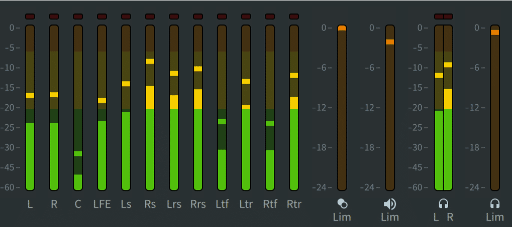
The speaker output meters provide metering of the speaker outputs for the active monitoring layout (as shown in the Room Configuration) when the Speaker Processing Option is enabled (in the Preferences or Settings Speaker tab). The display shows the meters for the current monitor layout only. Signal levels display in decibels relative to full scale (dBFS) and are not affected by the monitor attenuation controls. The speaker output meters are displayed pre-limiter.
The Headphone meters are displayed when the Headphone Processing Option is enabled (in the Preferences or Settings Headphone tab) and will display L R when stereo is selected as the Render mode or BIN when Binaural is selected. As with the speaker output meters, the signal levels display in dBFS.
All three limiting meters (spatial coding, speaker, headphone) display the amount of limiting applied in dBFS when the respective limiters have been enabled in Preferences or Settings.
Limiting affects monitoring at the outputs only. It does not affect what is recorded to the master during master recording. The speaker output limiting applied is designed to provide an accurate representation of the limiting that will be applied during encoding to Dolby Digital Plus JOC and prevents hard clipping. The option to switch off limiting is provided mainly as a diagnostic tool. It is recommended that output limiting be left on.
At times, the Output Meters section may display red clip indicators at the top of any meters that have been overloaded with signals that exceed full-scale audio. Clear any clips that are displayed in the main window meters by clicking the red clip indicator.
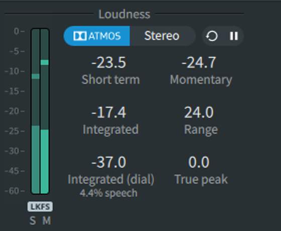
Loudness Measurement
Real-time loudness measurement is available in the Renderer window. This is enabled by default in Preferences or Settings. Once enabled, loudness measurement is active when the transport is moving, either chasing LTC or during playback with a master file loaded.
Click the markers (i) to familiarize yourself with the various parts of the Loudness Measurement section.
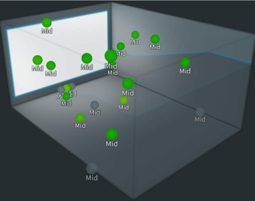
Object View
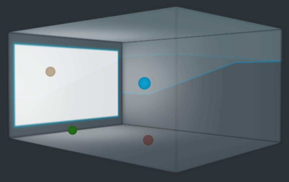
The Object View, in the lower right side of the main window, displays either a virtual Theater or Person (head view), depending on personal preference. These views provide a visual representation of Object position, size, and signal level, as rendered by the Dolby Atmos Renderer.
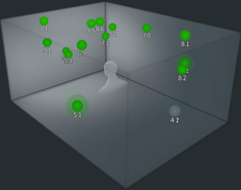
The Object View can also display the Object numbers, Binaural settings, or Standard groups.
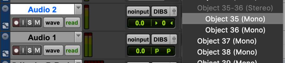
The Object numbers display (shown here) can be helpful in visually correlating the Pro Tools panner with an input.
The Binaural settings view (shown here) displays the distance settings per Object as set in the Binaural Render Mode settings window.
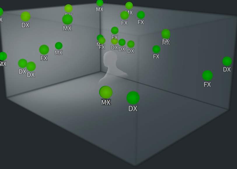
The Standard groups view (shown here) displays Objects’ membership to one of the default groups set in the Input Configuration window. Objects assigned to the Dialog, Music, Effects, or Narration groups will display their affiliation in this view. Objects assigned to the Dialog group will be displayed as DX, Music as MX, Effects as FX, and Narration as NR. Objects assigned to user-created groups will be visible, but the user-created group names will not be displayed.
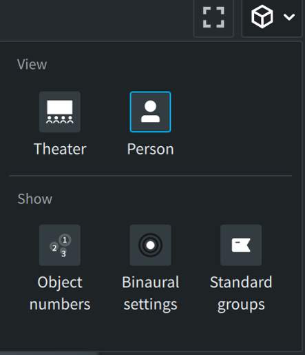
Accessing the Views and Settings
The different Object Views and settings are accessed by clicking on the cube icon within the Object View area of the UI to reveal the View/Show panel (shown here).
The square icon to the left of the cube icon toggles the Objects View to full screen and back.
Object Colors
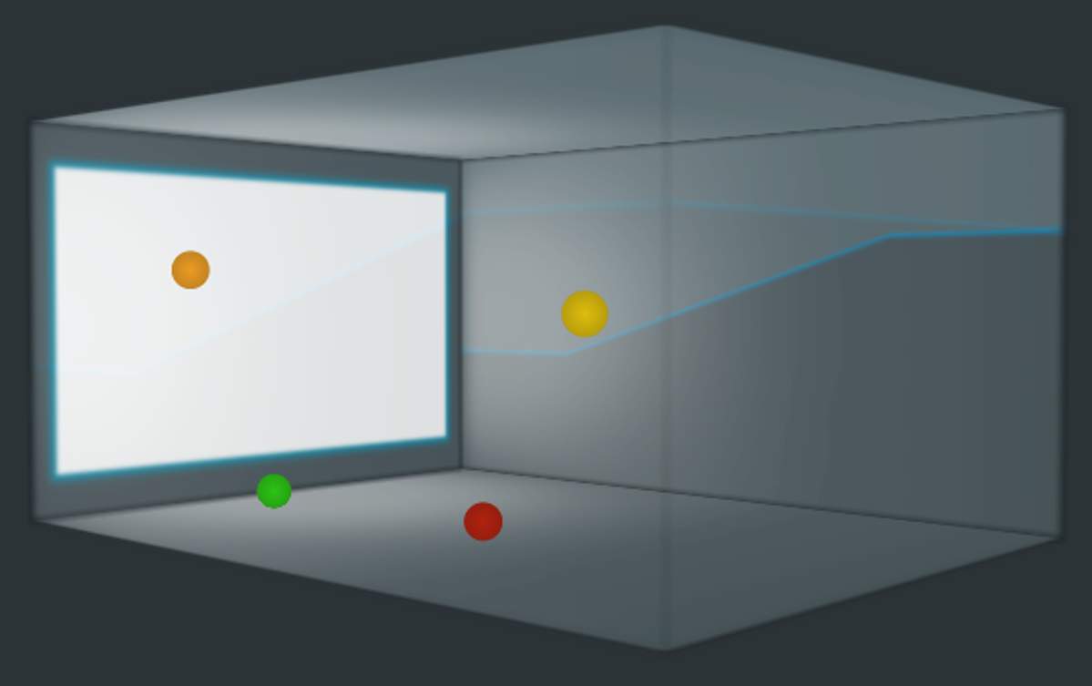
Objects are displayed using various color states.
Objects will be colored to indicate that they have a signal. The Object color represents the signal level using the same color range as the Input Status, Room Configuration, and Meters.
An Object will become completely transparent if it has no signal level.
Object Automation Color
Objects will also change their display during automation. An Object that is currently touched for automation will turn blue.
All other Objects that have signal level will retain their color but become slightly transparent while the target Object is being touched for automation.
Object Size
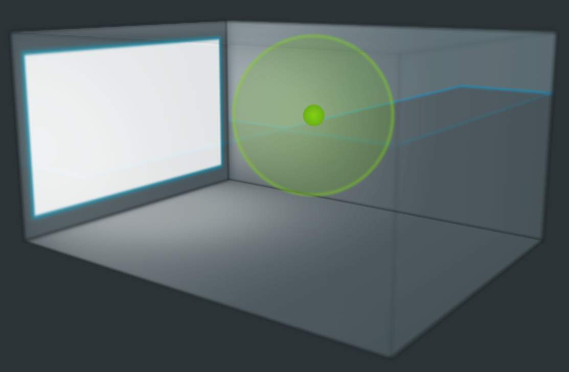
Object size displays as a halo around the Object. As the value of the Object size increases or decreases, the halo increases or decreases in size proportionally.
Rotating the Object View
The Theater View has a white rectangle on one side to represent the front screen. The left-side, right-side, and back walls are represented by transparent rectangles. The Theater or Person displays can be rotated to change the visual perspective.
To rotate the Theater or Person View, do the following:
- Click on the boxed area and drag left, right, up, or down.
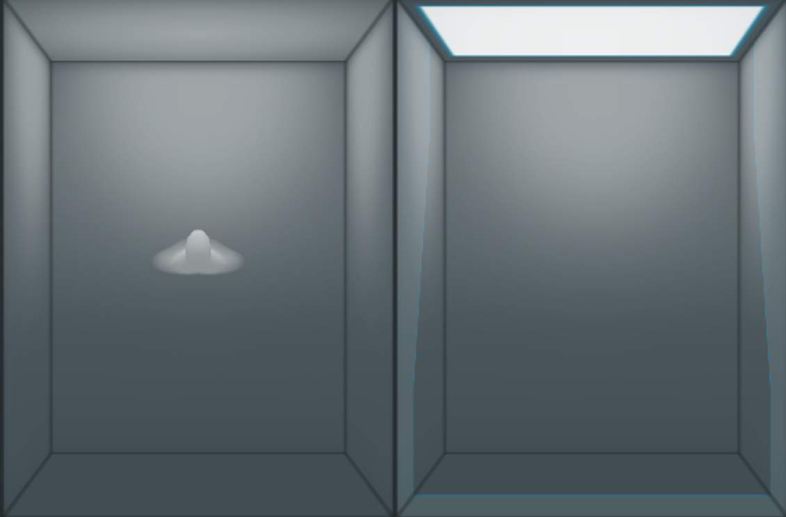
To display an overhead view of the auditorium and available Objects, do the following:
- Double-click anywhere in the Objects View. The view will instantly switch to an overhead view, with the front screen displayed at the top.
To return from overhead view, double-click anywhere in the Objects View again. The display will instantly switch back to the state it was in prior to initiating overhead view. If desired, zoom in and out on the Object View using the scroll wheel on a mouse or a scrolling gesture on a trackpad.
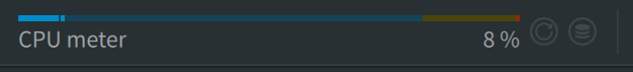
CPU Meter
The Renderer includes a CPU meter and indicators to help monitor high processing loads.
Click the markers (i) to familiarize yourself with the various parts of the CPU Meter section.
Input / Master Status
Starting with Renderer v3.7, users have the ability to set the Input Configuration, Binaural Render Mode settings, and Trim and Downmix settings of the input independent of the settings of an open Master file. This allows for the use of settings plug-ins to control Input Configuration and Binaural Render Mode settings as well as allowing the user to audition different trim and downmix settings. The settings used in the Input Configuration, Binaural Render Mode and Trims and Downmixes can be copied from an open Master file. In addition, changes to program level metadata can be copied from the input to an unlocked Master.
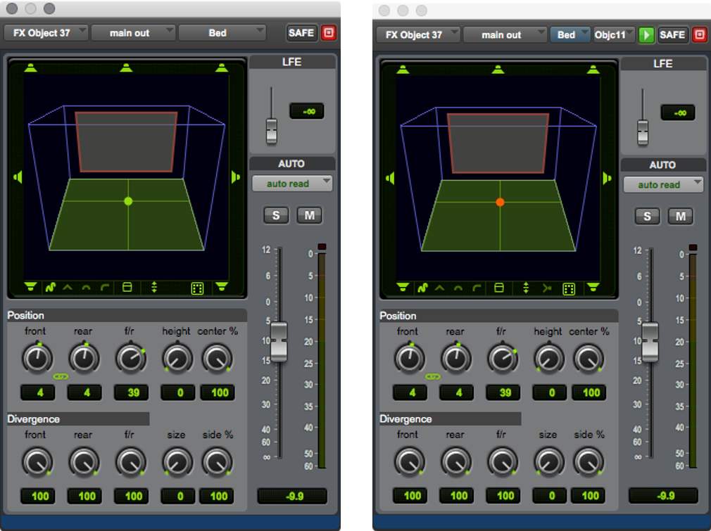
To avoid confusion, the Renderer main window has status indicators in the lower left of the Renderer main window to alert the user when any settings differ between the Input and an open Master.
As pictured below, all three are set independently.

Renderer Input Configuration
Lesson 3 of 6
The default input configuration in the Dolby Atmos Renderer assigns the first 10 inputs to a 7.1.2 Bed and the remaining 118 inputs as Objects, for a total of 128 inputs.
The use of a single 7.1.2 composite Bed is sufficient for many projects. However, greater flexibility can be achieved with custom input configurations that allow for multiple Beds, as well as Bed and Object inputs grouped together into stems.
- bulletBeyond making the input configuration clearer by splitting inputs into groups, these types of configurations also facilitate the ability to create stem re-renders without multiple mastering passes, and allow for export of an ADM BWF master geared for localization work.
- bulletGrouping Renderer inputs also makes working with multiple playback systems simpler (possible when using a Dolby Atmos Mastering Suite license on an external Renderer), as Dialog, Music, and FX playback systems, for example, can address clearly defined and labeled inputs.
The I/O setup in Pro Tools must match the input configuration of the Renderer. This can be done manually, or by choosing Default > Use Atmos Renderer in Pro Tools I/O setup, which will load the current input configuration from the Renderer directly.
Input/Master Switch
Version 3.7 of the Dolby Atmos Renderer introduces the Input/Master switch, which decouples the input configuration from that of an open Master file.

With the Input/Master switch toggled to Input, it is now possible to adjust the input configuration as needed, independent of an open Master file, and configure Pro Tools and the “Input” of the input configuration for monitoring. An open Master file will no longer result in Renderer inputs being unavailable. It is also possible to copy the input configuration from an open .atmos Master file to the “input” to enable punching into it or for use in creating a new Master file. Conversely, program level metadata updates, including group definitions and membership, can be copied from the “Input” to an open .atmos Master file to update these settings in the Master file.

Input/Master Status Indicator
If the Input and Master sides of the input configuration do not match, an orange indicator will be visible in the bottom left of the Renderer main window.

This indicator will turn off when the “Input” and “Master” match, indicating that punch-ins to the open Master are permitted.
Modifying the Input Configuration
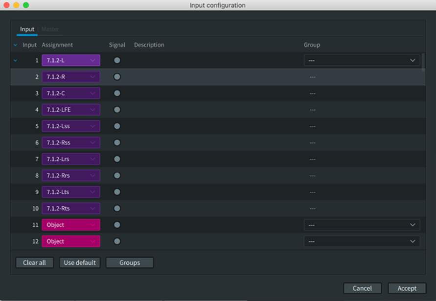
Open the Input Configuration window from the menu bar by choosing Window > Input Configuration or by pressing Command+I (Mac) or Ctrl+I (Windows).
The columns across the top of the Input Configuration window are labeled:
- Input – 1 to 128
- Assignment – Input assignment
- Signal – The same colors (green, yellow, red) are used in the main Renderer window to indicate input level.
- Description
- Group
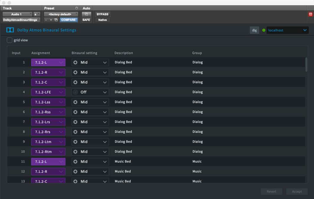
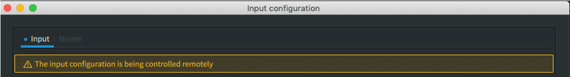
If the Binaural Settings plug-in is in use in Pro Tools, the Input side of the the Input Configuration will be controlled remotely, as discussed in the Binaural Settings plug-in section later in this section.
Assigning an Input
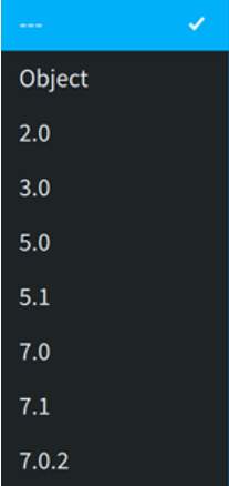
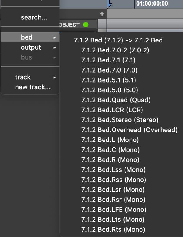
Clicking any input assignment allows changes to the existing input assignment from a drop-down menu.
An input can be set as:
- Unassigned
- As an Object
- As the first (left channel) of a Bed
- Bed widths can be (2.0, 3.0, 5.0, 5.1, 7.0, 7.1, 7.0.2, 7.1.2)
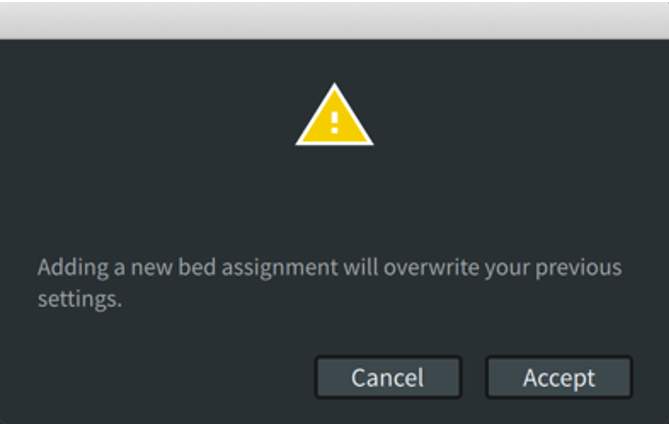
Assigning an input to a Bed will overwrite the assignments to subsequent channels of the Bed width; e.g., assigning Input 11 to a 7.1.2 will overwrite the assignments for inputs 12–20. A warning dialog box will appear confirming this.
Note the following in regard to input assignment:
- Any inputs can be assigned to Beds. They do not have to precede Object assignments. Beds and Object assignments can be interspersed to keep stems together. Again, the Pro Tools I/O and Renderer Input Configuration must match.
- Changing assignments will overwrite existing input descriptions and Group membership.
- Inputs assigned to a Bed can be displayed as expanded or collapsed using the arrow to the left of the first input assigned to that Bed.
- The input configuration is written to the master file and will be loaded along with the file. Input configurations can also be exported as part of a file that includes Binaural and Re-render configurations.
Adding a Description
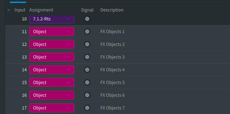
The fields under the Description column are free-form text fields allowing for sequential numbering of contiguous Object assignments. When Pro Tools is connected to the Renderer, up to 32 characters from this field are displayed in the Pro Tools I/O Setup Bus page in the Mapping to Renderer column. Input descriptions are useful for keeping Pro Tools sessions and the Renderer input configuration organized.
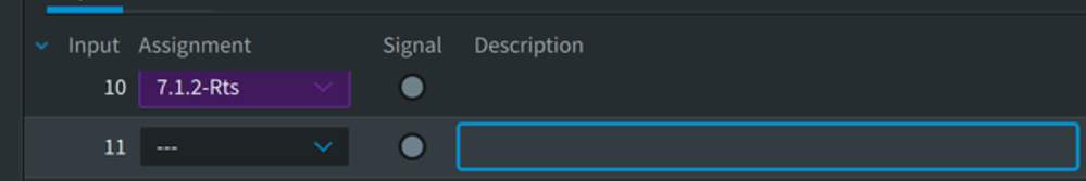
To enter a description:
- Click within the input under the Description column header to bring up the entry box (defined by a blue outline).
- Type in a description and press enter when finished.
To use sequential numbering in the description field for contiguous object inputs:
- Click the input assigned to an Object; the input will highlight in grey.
- Shift-click another input to highlight a range of inputs assigned to Objects.
- Click within the first highlighted input under the Description column header to bring up the entry box defined by a blue outline.
- Type in an entry followed by a number, e.g., FX Object 1.
- Hold down Control+Option+Command and press the Return or Enter key on the keyboard.
- The highlighted inputs will share a description followed by incremented numbering.
Inputs assigned to Beds can be selected in the range as well but will not have numbering applied.
Play Video
Assigning Inputs to Groups
Groups are used to group together a collection of Beds, Objects, or both for re-rendering. The primary use of groups is to create channel-based stem outputs by grouping the bed and objects for a specific stem together, e.g, Dialog or FX.
Group assignments can be made to an existing .atmos master file that is unlocked for editing.
To assign an input to a group:
- Click any input under the Group column header to bring up the drop-down menu of available groups.
- Choose a group to assign to the input.
Multiple inputs can be assigned to a group at the same time by using Shift-click to highlight a selection of inputs prior to the group assignment. This method is used to assign a bed and objects to a Group.
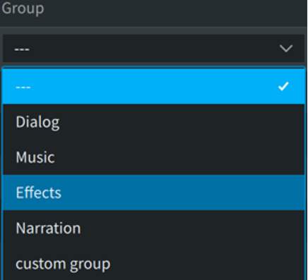
By default, the groups list is pre-populated with four Standard Groups commonly used in post-production: Dialog, Music, Effects, and Narration. You can also add or delete custom groups.
Custom Groups can be added to or modified on an existing .atmos master file that is unlocked for editing.
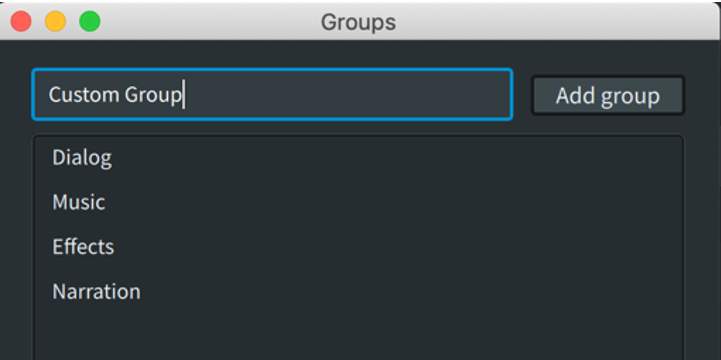
To add a custom group:
- Click within the free text field defined by a blue outline.
- Enter the custom group name and click Add group.
The custom group name will now appear in the group list and in the available group list drop-down menu when assigning inputs.
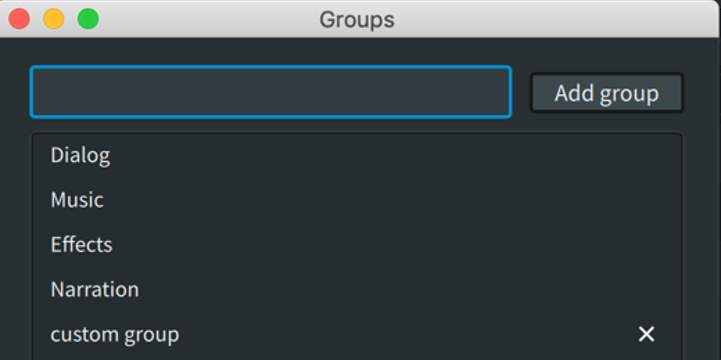
To delete a custom group:
The custom group displays in the list with an x next to its name, indicating that it can be deleted.
- Click on the x to delete a custom group.
If any inputs are currently assigned to a custom group, a warning dialog will appear.
Any input assignments to the Standard Groups of Dialog, Music, Effects, and Narration can also be optionally displayed in the main Renderer Window > Object View.
Other Configuration Window Functions
- bulletClear all: Clears all input assignments. There is no warning dialog.
- bulletUse default: Reverts to inputs 1 through 10 assigned to a 7.1.2 Bed and inputs 11 through 128 assigned to Objects. There is no warning dialog.
- bulletGroups: Opens the Groups dialog for adding, deleting, or editing groups.
The input configuration is written to the master file and will be loaded along with the file. Input configurations can also be exported as part of a file that includes Binaural and Re-render configurations.
The Dolby Atmos Binaural Settings Plug-in
The Dolby Atmos Binaural Settings plug-in can be used to make input assignments remotely from Pro Tools. Other functions of this plug-in are discussed in a subsequent section.
This plug-in can be inserted on any mono or stereo track and establishes communication with the Dolby Atmos Renderer independently of Pro Tools. This is done by entering the IP address or hostname of the external Renderer or entering localhost if the Renderer is running internally.
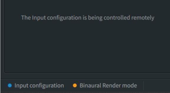
Status indicators appear in the lower left corner of the Renderer UI for both Input Configuration and Binaural Render Mode.
These will either illuminate blue (connected, remote control is applied to input, and plug-in and master are the same) or orange (plug-in settings differ from an open master).
This is also indicated in the Input Configuration window.
With an editable master file open, use the Copy settings from Input to Master button from Input Configuration window to conform the master. Changes made to Group assignments from the settings plug-in can also be written to an open editable master file from the Input Configuration window using the Copy groups from input to master. Once done, the corresponding status indicators in the main Renderer window will change to blue.
Speaker Calibration
Lesson 4 of 6
The Dolby Atmos Renderer provides the ability to adjust speaker gain and delay (globally and individually) and use the onboard signal generator. With the Dolby Atmos Renderer running as the Dolby Atmos Mastering Suite, EQ function per speaker is added as well.
When using the Dolby Atmos Renderer with a monitor control system, these functions are likely duplicated. As with Bass Management, it may make more sense to perform gain/delay and EQ in the monitor control system rather than the Renderer to provide consistency when monitoring other sources.
While speaker placement and room tuning are outside the purview of this course, basic calibration with pink noise and an SPL meter can be performed using the onboard signal generator.
The Speaker Calibration Window
Use the controls in the Speaker Calibration window to calibrate the room on a global or speaker-by-speaker basis. Gain, Delay, and Equalization settings (Mastering Suite only) can be adjusted to achieve proper levels, timing, and tone matching the monitoring chain.
You can access the Speaker Calibration window from the main window menu bar, or by pressing Command+K (Mac) or Ctrl+K (Windows).
The Speaker Calibration window (as shown below) is divided into three sections: Gain/Delay, Speaker EQ (Mastering Suite only), and Signal Generator. The Gain/Delay and Speaker EQ tabs provide a visual representation of the physical speakers defined in the Speaker tab of the Room Setup window.
Speaker EQ settings are discussed in the PT210D course.
Click the Markers (i) to familiarize yourself with the various Speaker Calibration features.
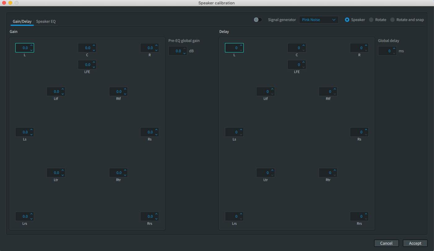
Gain/Delay Settings
Gain and Delay for individual speakers can be adjusted as needed by highlighting the speaker output and typing in a new value or by clicking the up/down arrows. Any changes are applied immediately.
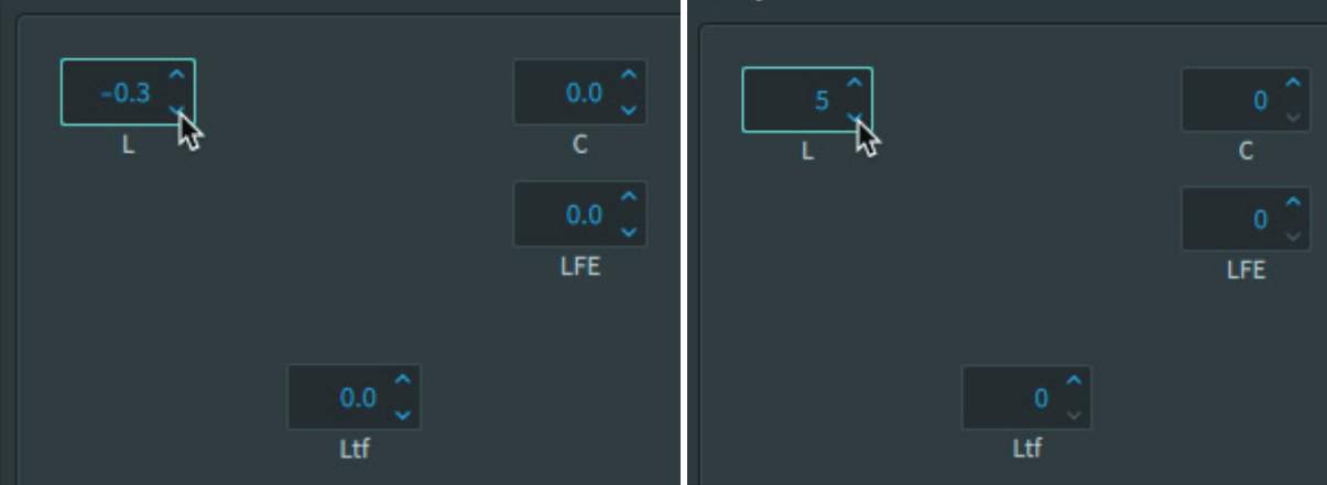
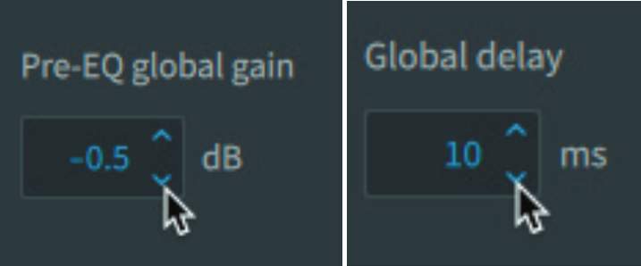
Global Gain/Delay settings can also be made.
Signal Generator Settings
The Signal Generator is useful for verification of output speaker routing as well as for calibration and tuning.
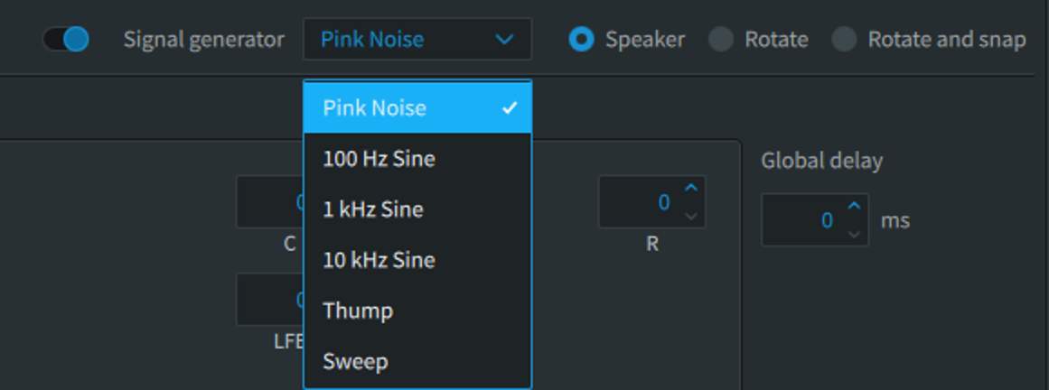
Signal can be sent to an individual speaker by clicking on it in the Gain, Delay, or EQ displays, or the speakers can be fed sequentially by turning on either Rotate or Rotate and Snap.
The main Renderer window interacts with the Signal Generator to provide a visual indication of which speaker is active. Rotate and Rotate and Snap pan using an Object as Renderer input 11, which is visible in the Object View.
A variety of source signals are available.
The playback level of test signals is impacted by the attenuation setting set in the main UI window. Be sure to have this set correctly prior to calibration.
Connecting with the Dolby Atmos Renderer
Lesson 1 of 7
Session Requirements
To be compatible with the Dolby Atmos Renderer, the Pro Tools session must conform to specific requirements:
- bulletSample Rate – The Renderer supports 48 kHz and 96 kHz sessions only. If working with different sample rates during sound creation or premixing, the session sample rate will need to be changed prior to working with the Renderer.
- bulletTimecode Rate – The Renderer supports creating masters from sessions with the following timecode rates: 23.976, 24, 25, 29.97, 29.97 drop frame, or 30 fps.
- bulletHardware Buffer Size – This setting should be at least 1,024 samples.
- bulletPlayback Engine – This should be set to HDX for the Dolby Atmos Renderer running on an external Rendering and Mastering Workstation, or set to Dolby Audio Bridge for the Dolby Atmos Renderer running internally. If Renderer Send and Return plug-ins are being used to work with the Dolby Atmos Renderer running internally, the Playback Engine will be HDX for monitoring and recording live Re-renders.
Setting the Dolby Atmos Renderer as a Pro Tools Peripheral
Before authoring Dolby Atmos content from Pro Tools, Pro Tools must be set up to communicate with the Dolby Atmos Renderer.
- 11With the Dolby Atmos Renderer already open, launch Pro Tools.
- 22In Pro Tools, open the Peripherals dialog box (Setup > Peripherals).
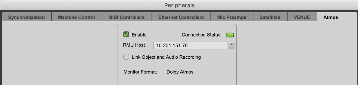
- 33Click the Atmos tab at the top right of the dialog box.
- 44Click the Enable checkbox so that it becomes checked. The Connection Status indicator will begin flashing green.
- 55In the RMU Host field, enter the IP address or hostname for the Dolby Atmos Renderer, or choose the Renderer from the drop-down menu. The Connection Status indicator will turn solid green once a valid connection is established.
The Enable Link Object and Audio Recording checkbox is a useful option when you want to record and monitor object audio and metadata simultaneously from another workstation in a source/recorder workflow.
In a source/recorder workflow, the Pro Tools recording workstation must be able to capture both the audio signal and the pan/size automation data coming from the playback workstation via the Renderer.
This does not apply in a single-DAW setup and this option should be disabled if it is not necessary to record audio and object metadata from another workstation.
Configuring Your I/O Setup
Lesson 2 of 7
The Pro Tools I/O settings must be configured to route signals to the Dolby Atmos Renderer. The exact configuration can vary, depending on the hardware used and the number of Beds and Objects required. Generally speaking, the Pro Tools I/O should be configured to match the default input configuration of the Renderer – the first 10 inputs for a 7.1.2 bed and the remaining 118 inputs for objects.
Setting Pro Tools Outputs
To gain a clearer understanding of the routing, let’s start from a blank slate by deleting existing Output and Bus paths from the I/O Setup:
- 11In Pro Tools, open the I/O Setup dialog box (Setup>I/O Setup) and click on the Bus tab.
- 22Click on one Bus and then press Command+A (Mac) / Ctrl+A (Windows), or otherwise select all existing Bus paths. Then click the Delete Path button. This will clear all preexisting Bus paths from the tab.
- 33Repeat this process in the Output tab, to clear all preexisting Output paths from the tab.
- 44In the lower left-hand corner of the Output tab of the I/O Setup dialog box, click on the Path Order selector, and set the 7.1.2 channel format to the SMPTE path order.
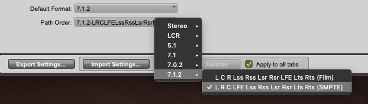
Outputs can manually be re-ordered in SMPTE order if this step is inadvertently skipped.
The Atmos Renderer uses SMPTE channel order for 5.1 to 7.1.2 beds. If recording Re-renders back into Pro Tools, SMPTE ordering must be used on both the Output tab and the Input tab. Do not change the channel order on the Bus tab, as this is used for internal routing in Pro Tools.
- 55Click New Path, and create a 7.1.2 output in the New Paths dialog box, named Bed.
- 66Create 118 mono paths named Object.
- 77When using the Dolby Audio Bridge to communicate with an Atmos renderer running on the same system, create a single mono path named LTC Gen Plug-in.
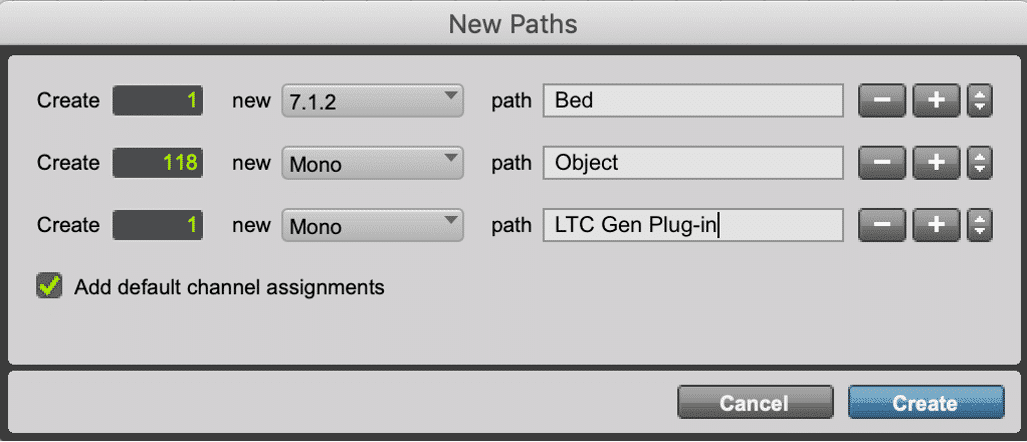
- 88Click the Create button.
Outputs can manually be re-ordered in SMPTE order if this step is inadvertently skipped.
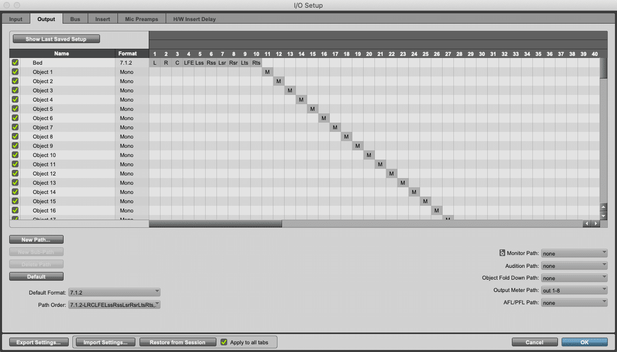
To communicate properly with the Dolby Atmos renderer, the order of the outputs is important—confirm the following:
- bulletThe Bed path occupies the first 10 channels of the Output tab.
- bulletThe objects are assigned individually to channels 11-128.
- bulletWhen used, the LTC Gen Plug-in is assigned to output 129
If you have multiple hardware interfaces connected, these may not necessarily start at Output 1.
Here’s the result so far:
When manually configuring I/O Setup it is also possible to create stereo outputs with mono subpaths that are mapped to the Renderer. This allows for both mono and stereo tracks to be used as Objects in the session. While this is more cumbersome to set up, it provides for greater flexibility. Setting up Pro Tools for using stereo and mono tracks assigned to stereo and mono Objects is covered in chapter 6 of this course.
Setting Up Pro Tools Busses
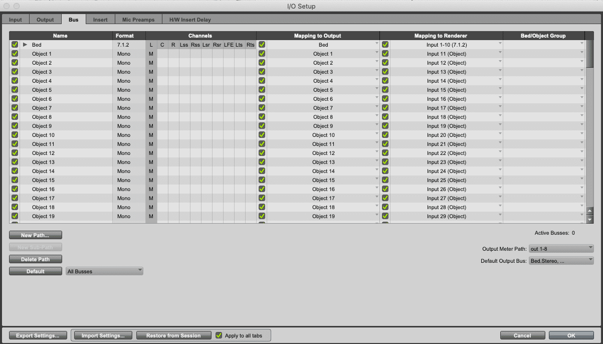
After having created the above outputs, the busses will be created automatically and named for the outputs with Mapping to Output already set in the Bus tab.
Assigning Beds
The next step is to map the Bed(s) and Objects to the Renderer:
- 11Click on Mapping to Renderer.
- 22In the Mapping to Renderer dropdown, select the Renderer input 1-10 (7.1.2).
If multiple beds are used, they should be assigned in sequential sets of outputs. Workflows involving multiple beds are discussed in the PT210D course.
Assigning Objects
Once the bed(s) are set up, the objects should be set up, with each object having its own channel. Doing this for each object can be time-consuming, but using cascading assignments will make this easier
- 11Using Shift+click, select the Busses Object 1 to Object 118.
- 22Holding Command+Option+Shift (Mac) or Ctrl+Alt+Shift (Windows), click on the Mapping to Object pop-up menu for Object 1, and select Input 11. This will sequentially map all Objects to their corresponding Renderer Inputs, beginning at Input 11.
Mapping to Renderer (and the ability to map Beds as well as Objects) was introduced in Pro Tools 2020.11 and replaces the Mapping to Object column used from Pro Tools versions 12.8 through 2020.10.
These steps ensure that panning and size metadata for each Object is mapped to the corresponding audio input to the Renderer. Additionally, it makes the Beds available in the Edit and Mix windows as a discrete output assignment category separate from Output and Bus.
Assigning Beds to the Renderer is not technically required to route Bed audio to the Renderer but failure to do so does bring up a warning dialog when clicking OK to exit the I/O setup, as this step is required for bouncing a mix to ADM BWF. This functionality will be discussed in the PT210D course.
Here’s the result.
Setting Track Outputs
Lesson 3 of 7
After the I/O and Object mapping is configured, the next step is to configure tracks for Dolby Atmos mixing. Start by creating one 7.1.2 track and either 118 mono tracks for Objects or a mix of stereo and mono tracks (adding up to 118 outputs) if stereo outputs were used in I/O Output tab.
Assigning Audio Tracks to Beds
With busses properly assigned in the Mapping to Renderer column in the I/O Setup Bus tab, Beds now appear in the Edit and Mix windows as a discrete output category separate from Output and Bus.
To assign a track to a bed:
- 11Click on desired track’s Output Path selector.
- 22Beds mapped to the renderer will appear in the bed category.
- 33Choose the desired bed path (or sub path).
Assigning Objects
The Object view in Pro Tools enables mono or stereo audio tracks to be assigned to Objects, toggled between assignment to Bus or Object, and where Object mode is switched to send or receive panning and size metadata to or from the Renderer.
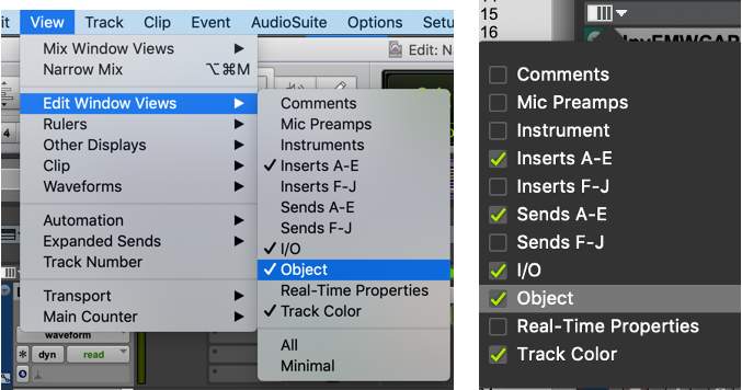
To show the Object Edit window view:
- bulletFrom the menu bar, choose View > Edit Window Views (or Mix Window Views)> Object.
OR
- bulletSelect Object in the Edit Window View (or Mix window view) selector.

The top of the Object column in the Edit window displays a connection status indicator that will show if a connection has been established with the Renderer. Green indicates a successful connection. Orange shows no connection. If this indicator is orange, the connection status should be checked in Setup > Peripherals > Atmos.
The Object View will be available for mono and stereo tracks. There are four controls accessible from the Object Column View:
Object Output Path Selector
Audio tracks to be used with Objects are assigned to busses mapped to Object outputs in the I/O setup via the Object Output Path selector.
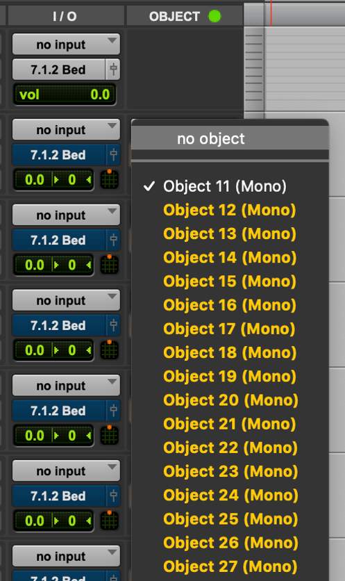
These busses feed Renderer inputs configured as Objects, and it is this allocation combined with the mapping to Object output in I/O Config which links each track’s Pro Tools panner to the matching Renderer input for correct metadata capture.
Object mapping in the Bus page of the I/O setup dialog box determines the availability of objects in this list. If the I/O setup uses mono outputs, the list of available Objects will appear as mono.
- If the I/O setup uses stereo outputs, a mono Audio track will display the available Objects as mono subpaths.
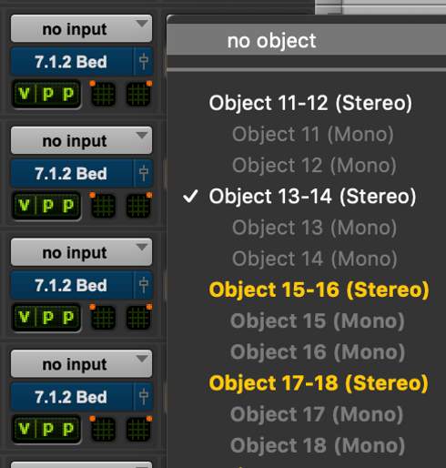
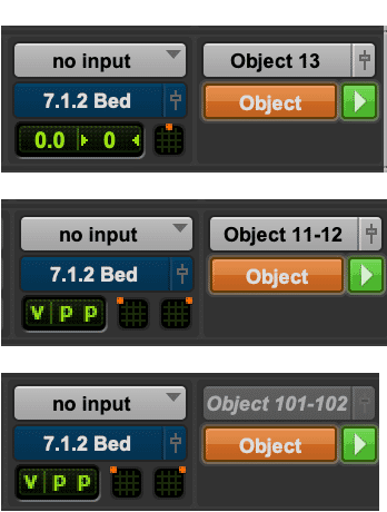
- A mono Audio track will show the assignment as mono regardless if the I/O setup uses mono outputs or stereo outputs with mono subpaths.
- If the I/O setup uses stereo outputs, a stereo audio track will show the assignment as stereo.
- If a master file is open in the Renderer, Objects not used in the master file can be assigned but will not be available (grayed out and italicized).
Bus/Object Toggle
Mono or stereo Audio tracks can be toggled between assignment to an Object or to a multichannel bus (mapped to outputs in the I/O setup that correspond to Bed inputs on the Renderer). This assignment can be automated in order for the audio to contribute to either a Bus or an Object at different points in time throughout the session.
For example, if an audio element has been pre-mixed in a Bed but warrants being made an Object, this can be done without having to move the audio clip elsewhere in the session. Clicking the Bus/Object Toggle (immediately below the Object Output Path selector) will change the track’s assignment.
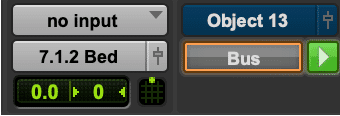
Holding the Option key (Mac) or Alt key (Windows) when changing one track will switch all mono or stereo tracks with Object bus assignments between Bus and Object.
The Bus/Object Toggle can be automated as well, if needed.
Object Control Mode
To the right of the Bus/Object Toggle is the Object Control Mode switch. This switch has three modes:
Master (Green play icon): Set by default if no other tracks are already assigned to the same Object.

Off (Gray play icon): Multiple audio tracks can be assigned to the same Object. However, only one audio track can be assigned as Master to write pan/size metadata to the mapped Object.

Record (Red record dot): Used to record Object pan/size metadata from the Renderer when using a Pro Tools workstation as a Master recorder with one or more additional Pro Tools workstations connected to the same Renderer. This workflow is available only when running the Dolby Atmos Renderer externally on an RMW.

Output Window button
Clicking the Output Window button (The fader icon to the right of the object assignment) will show a panner for the track. This is the same as clicking the Output Window button (fader icon) from the I/O column.

Synchronizing Pro Tools and an Internal Renderer
Lesson 4 of 7
In most cases, the Dolby Atmos Renderer follows (or chases) the Pro Tools transport. When the Renderer is running on the same workstation as the DAW, the synchronization source is LTC or system synchronization when using the Send/Return plug-ins.
The timecode rate of the session as set in the Session Setup dialog box must match the frame rate set in the Renderer Preferences Driver page, or the loaded Master File.
Using the Dolby LTC Generator Plug-In
The Dolby LTC Generator plug-in can be used for both the external and internal Renderer use cases. The LTC Generator plug-in requires the timecode rate to be set prior to use and will follow the session transport.
To use the Dolby LTC Generator:
- 11Create a mono Auxiliary Input track.
- 22Instantiate the Dolby LTC Generator plug-in on an available insert.
- 33Assign the output of the track to a dedicated bus—depending on the configuration, this bus should be mapped to output 128 for use with an external Renderer or 129 for use with an internal Renderer.
Note that when using LTC over Audio assigned to an Object, that Renderer input is not available for Bed or Object audio.
Using LTC Files
It is possible to use LTC as mono .wav files in a session. These can be generated by recording the LTC output of the SYNC HD, and after accurately trimming the file, used on a mono audio track in the same manner as the LTC Generator plug-in.
This is not a preferred approach, as a clip on the timeline may be prone to being slipped or nudged, and overall sync may be impacted by delay compensation settings in the session.
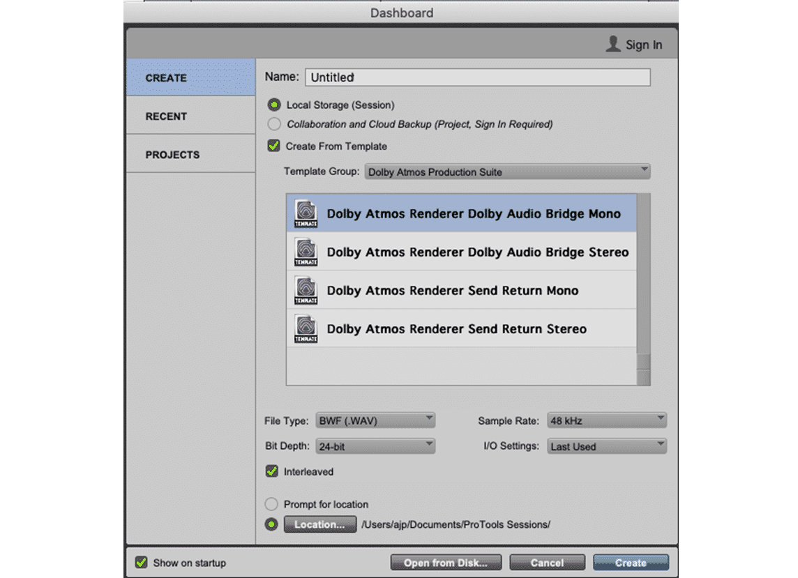
Using the Supplied Templates
Lesson 5 of 7
The supplied Pro Tools templates are the fastest way to get a session started and set up to create Dolby Atmos content. As discussed in Lesson 2, Dolby Renderer Installer Components, the Renderer comes with four templates that are installed and accessible when creating a session: When the Create from Template box is checked, they can be found in the Dolby Atmos Production Suite template group.
The Dolby Audio Bridge templates can also be used when HDX is to be used as the Playback Engine in conjunction with the external Dolby Atmos Renderer, as the setup is the same, other than the output device selected.
Loading .pio Files
When using the Dolby Audio Bridge templates, the corresponding mono or stereo I/O file (.pio) should be imported in the I/O Setup dialog box to ensure the bussing and output mapping is set correctly. This can be done from the Dashboard by selecting the I/O settings that correspond to the template from the I/O Settings dropdown menu.
Using the Renderer Send/Return Plug-in Templates
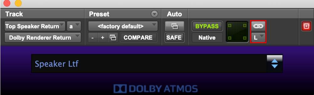
The Renderer Send/Return plug-in workflow is the original way that Pro Tools interfaced with the Dolby Atmos Renderer on the same workstation. This workflow has since been supplanted by the use of the Dolby Audio Bridge. However, the Send/Return plug-in workflow is still used by some, as it allows for recording Re-renders.
The Dolby Audio Bridge is not bi-directional, whereas the Renderer Send/Return plugin workflow allows bi-directional audio to/from the Renderer and allows for use of HDX DSP for plug-in processing.
To use the Renderer Send/Return plug-ins, the driver in the Renderer Preferences must be set to Send/Return plug-ins.
The Renderer Send/Return plug-ins do not map busses to outputs in Pro Tools I/O Setup, as the plug-ins route audio directly to the Renderer without using physical Pro Tools I/O. Instead these templates use two sets of aux input tracks to enable send/receive of audio from the Renderer.
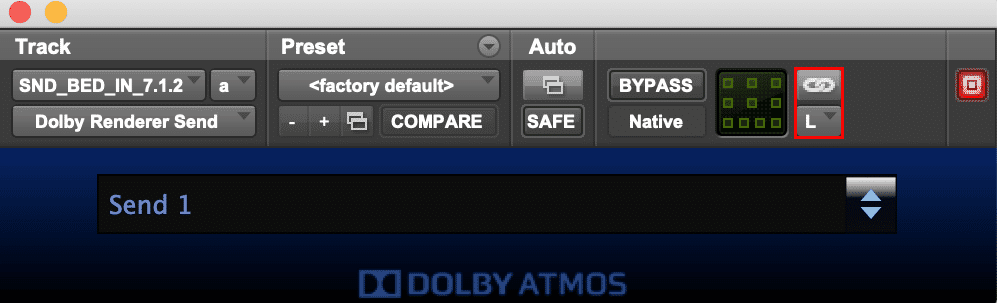
The first set of aux input tracks is used with the Renderer Send plug-in to route audio to the Renderer.
The aux input tracks with the Renderer Send plug-in use the Bed and Object busses as input with a dummy output. The audio is sent to the Renderer via a software connection as opposed to a physical Pro Tools output; however, an output is required to be set on the aux input track in order for the plug-in to pass audio. This set of aux input tracks is hidden by default.
The second set of aux input tracks is used with the Renderer Return plug-in to route the speaker and headphone outputs from the Renderer to the Pro Tools audio interface via the I/O Setup. In addition to the monitor output, these can be used for returning Re-renders to Pro Tools for recording, or for real-time loudness measurement, for example. These aux input tracks require a dummy input to be set.
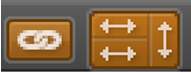
When using either the Renderer Send or Return plug-ins on multichannel tracks (5.1, 7.1, 7.0.2, 7.1.2), the Master Link button must be disabled and the Channel Selector drop-down used to individually select and assign Sends to each channel, so that SMPTE channel ordering is maintained for input and output to/from the Renderer.
Working with Single or Multiple Beds
Lesson 1 of 6
The first ten inputs to the Renderer are dedicated to Bed audio input. Beds are configured in the I/O setup of Pro Tools and in the Renderer Input Configuration Window. The Renderer defaults to a single 7.1.2 Bed; however, a smaller Bed width can be used.
Alternatively, Objects alone can be used (the first 10 channels will still be reserved for Bed audio), or Pro Tools and the Renderer can be configured to use multiple Beds to facilitate a traditional stem-based workflow.
The decision on whether to use a single composite Bed and leave 118 Renderer inputs available for Object audio, or to use multiple Beds with fewer Renderer inputs available for Object audio, is dependent on the mixer’s preferences, the content, and workflow considerations.
For some projects and workflows, the flexibility of having more inputs available for Objects is outweighed by the inefficiency of having to perform multiple mastering passes (selectively muting tracks in Pro Tools) in order to derive channel-based stem re-renders. For some projects and workflows, the simplicity of a single Bed and the availability of 118 Objects makes sense.
Single Composite Bed Output
If the decision is made to go with a single composite 7.1.2 Bed (as per the default Renderer Input Configuration and supplied templates), this does not restrict the flexibility to work with stems within Pro Tools. As long as audio leaves Pro Tools as a combined 7.1.2 output routed to the first ten Renderer inputs, there are no restrictions on how the Pro Tools session is laid out and routed internally. For example, each stem may be assigned to a 7.1.2 aux input track with audio tracks of any width feeding each stem as needed. These may be summed to a single 7.1.2 aux input before output if bus processing is desired, or may be bussed to the main 7.1.2 output for summing.
Multiple Bed Outputs
Within the DAW, mixers often group similar audio together into stems. In post-production work, the stems typically include Dialog, Music, and Effects. Other types of stems might include Narration, Foley, etc. In music production, stems could include Drums, Guitars, Keyboards, Vocals, etc. When working in Dolby Atmos, mixers can use multiple Bed tracks (one or more) for each stem.
Using multiple Beds configured as outputs in the Pro Tools I/O Setup and inputs in the Dolby Atmos Renderer Input Configuration facilitates the creation of channel-based stem re-renders without requiring multiple passes. It is also required when using multiple DAWs feeding Beds and Objects to the Dolby Atmos Renderer simultaneously.
Using multiple Beds requires some planning for track layouts in the session to ensure that the DAW I/O setup matches the input configuration of the Dolby Atmos Renderer. The Bus/Object toggle on Pro Tools audio tracks may also be utilized to assist with a reduced input count available to Objects due to multiple Beds being used. It is important also to understand that multiple audio tracks can be assigned to the same Object, though only one track can be enabled for Object control at any one time.
Setup of the I/O configuration can be done independently in Pro Tools I/O setup and the Renderer. I/O can also be configured in the Renderer and “ported” over to Pro Tools by selecting Default > Dolby Atmos Renderer on the Pro Tools I/O Setup output page. The only downside to using the Dolby Atmos Renderer as the default is that all Object audio will be configured as mono.
Even if the setups are configured in Pro Tools and the Renderer independently, the description in the Renderer Input Configuration will be present in Pro Tools I/O setup bus page in the Mapping to Renderer column, which is very helpful for organization.
The most common configuration is to create multiple Beds sequentially, followed by Objects. However, there is no reason that Beds and Objects cannot be interspersed in the I/O setup and input configuration, if desired.
Four-Bed configuration
Here’s an example of a four-Bed configuration with 7.1.2 for Dialog, Music, and Effects as well as an LCR Bed for Narration.
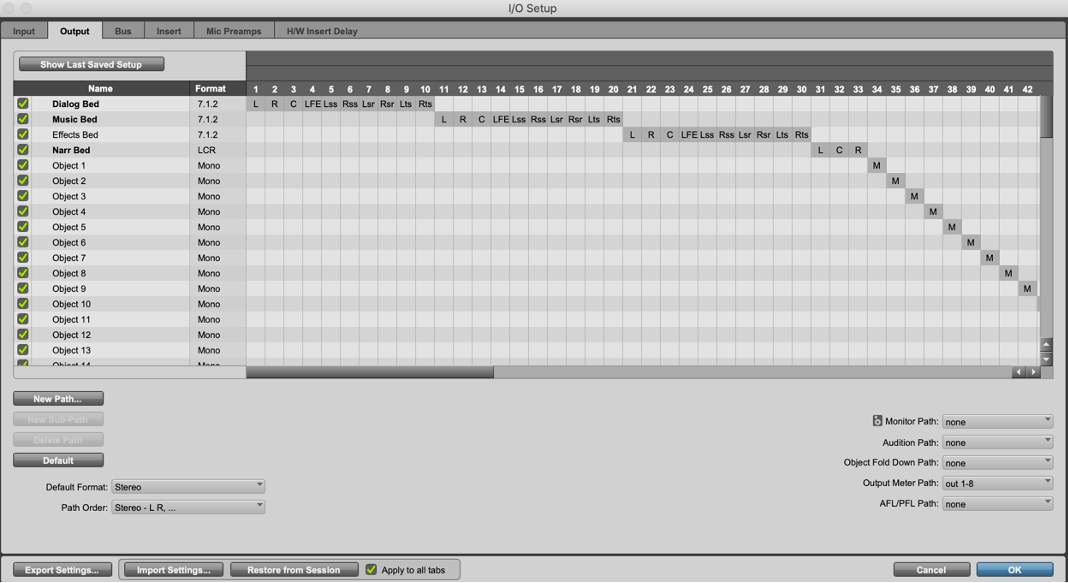
The I/O Output page configured for 3 x 7.1.2 Beds, 1 x LCR Bed, 95 Objects
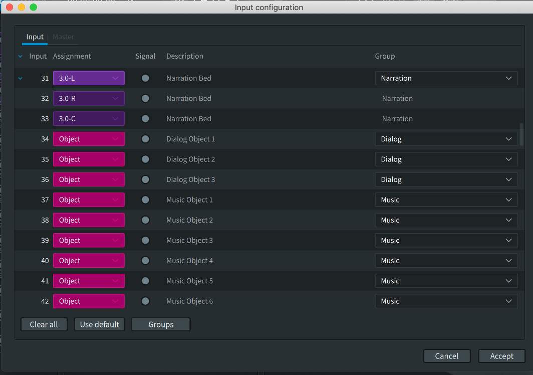
Renderer Input Configuration set for 3 x 7.1.2 Beds, 1 x LCR Bed, 95 Objects
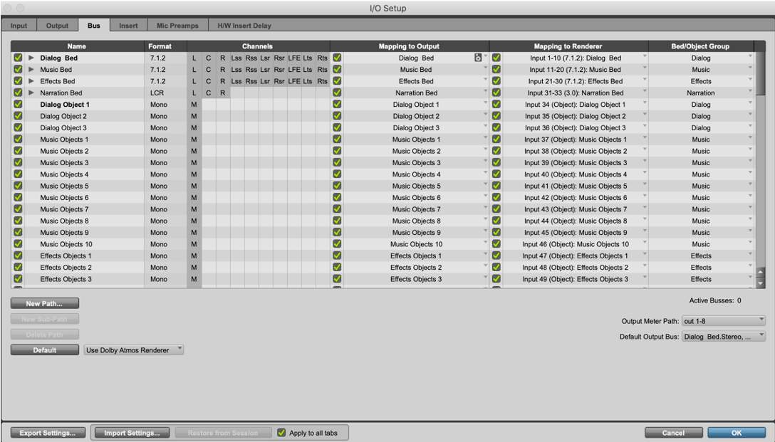
I/O Bus Page with Busses mapped to the Renderer using Input Descriptions and Group assignments as configured in the Renderer
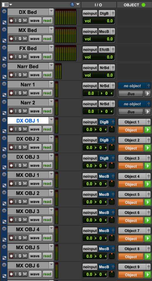
Edit Window with Beds and mono tracks assigned to Objects
Bed Tracks for Reverb Returns and Other Plug-ins
There are a multitude of different reverbs and plug-ins for use with 7.0.2 and 7.1.2 track widths in Pro Tools.
When working in Dolby Atmos, multichannel reverbs can be shared between multichannel Bed tracks and Object tracks using similar send-and-return routing to that used in traditional surround formats. These can return to their own 7.1.2 aux inputs bussed to the composite Bed output, a stem output, or their own Bed output.
If the Object track’s reverb can work effectively with generalized pan positioning, then a 7.1.2 return to the appropriate Bed is usually the best option. An added benefit of this configuration is that both Bed tracks and Object tracks can share the same reverb using a traditional send-and-return configuration, although it does mean that the Object’s reverb will be present in the Bed without the dry source Object present. A 7.1.2 re-render from the Renderer is therefore required in order to provide a complete stem, with Object and Object reverb rendered and present.
To apply reverb to an Object track and return the reverb to a 7.1.2 Bed:
- Create a 7.1.2 aux input track and insert the desired reverb plug-in on the track.
- Create a new 7.1.2 bus in I/O Setup for use as a reverb send path, and allocate this as the input to the aux input track. Route the output of the aux input track back to sum with the appropriate Bed track, such as the main 7.1.2 Bed or a 7.1.2 stem/group Bed.
- On the Object track, create a send to the 7.1.2 aux input track. The send fader can then be used effectively as a wet/dry level control. In most cases, you’ll want to enable Follow Main Pan (or FMP) in the send’s panner so that the Object panning metadata will be applied to the send pan position.
Play Video
Using Stereo Tracks for Objects
When creating a Dolby Atmos mix, stereo sources can be assigned to stereo Objects. This can be somewhat confusing to configure, as the Renderer treats all Object inputs as mono. In addition, the Pro Tools I/O Setup only supports bus mapping to mono Object paths. Subpaths are used to combine two mono Objects into a single stereo Object output path. If using the stereo Object templates, this is already configured, as the outputs are stereo.
To configure this manually from a setup that uses mono outputs:
- 11Delete the mono outputs to be replaced by stereo outputs.
- 22Create a new Stereo output path in the I/O Output page by checking Create Default.
- 33Name the path with the Object numbers you want to convert for Stereo or Mono use.
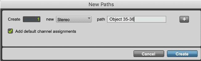
- 44Verify or move the output assignments to the proper outputs.
When expanded in the bus page, the new path will reveal the subpaths that can be mapped to Objects.

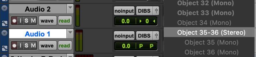
In the Edit window Object column, the stereo Object assignment will be available from a stereo Audio track…
…and the subpaths as mono Object assignments from a mono Audio track.
Play Video
Object/Bus Toggle Automation
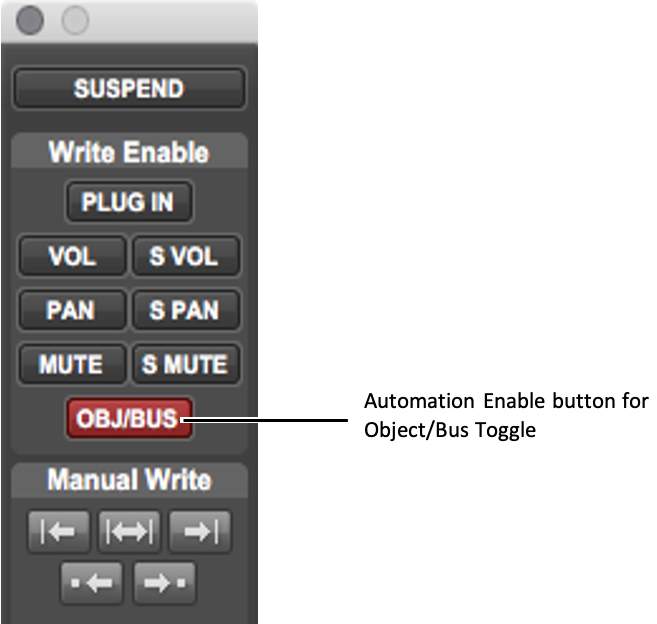
The Object/Bus Toggle setting can be automated on Object tracks. To facilitate writing Object/Bus Toggle automation for Object tracks, this parameter must be enabled in the Automation window (Window > Automation).
To prevent Object/Bus Toggle automation from being written, or to protect existing Object/Bus Toggle automation from being overwritten, you can disable this parameter in the Automation window.
The Object/Bus Toggle button enabled (red) in the Automation window
Using Groups and VCAs
Lesson 2 of 6
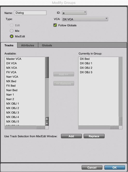
When working with sets of related tracks, such as FX bed tracks and object tracks, creating mix groups provides a way to link relevant parameters. Within the Modify Groups window in Pro Tools, Object Controls can be enabled, if required, under the Attributes and Globals tabs. This will group the Object control mode settings and Bus/Object toggles for all tracks in the group.
Whether this is useful or not depends on the mix in question; the Bus/Object toggle may be found to be of more use when adjusted on individual tracks rather than on a group. Parameter grouping may be useful, however, if multiple objects are used to layer sounds to create a single overall FX, where grouping identical track attributes such as panning may be desirable. Enabling groups for mutes while using stems may be useful if a single bed is being used and multiple mastering passes are required.
Groups can also be used to gang plug-in parameters in a specific insert slot. This can be very helpful in applying consistent control of compressors, limiters, filters, and EQs on multiple Objects.
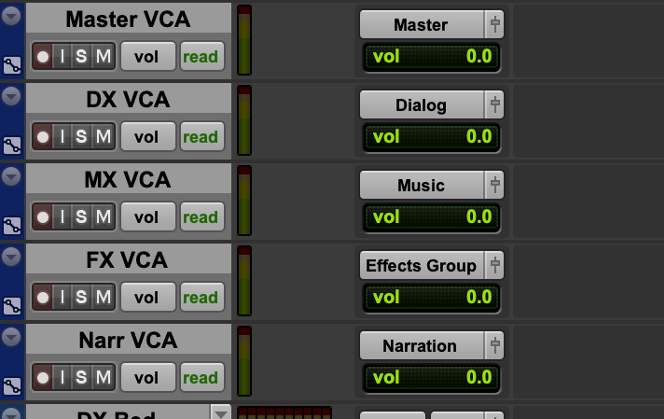
Using VCAs to Meet Loudness Targets
Controlling levels of a Dolby Atmos mix to meet loudness target levels (as measured by the Renderer or third-party plug-in via a 5.1 Loudness Re-Render) can be difficult. An effective method to control outputs is to assign stem groups to VCAs for level control of individual groups, and to create a master group comprised of the stem VCAs assigned to its own VCA for overall output level control.
Be aware that VCA’s used in this way can affect existing dynamics processing. It is important to be cognizant of the session’s bussing structure in determining the proper assignment of tracks to VCAs pre- or post- dynamics processing and to be aware of how this could alter the balance between Beds and Objects. When used judiciously, VCAs provide an effective method to “trim” an entire session to help achieve loudness targets.
Panning Parameters
Lesson 3 of 6
7.0.2, 7.1.2, and Object Panner
When a mono or stereo track is assigned to a 7.0.2 or 7.1.2 output bus, or to an Object output path, Pro Tools will use the 7.0.2, 7.1.2, or Object panner.
Pan Controls and Indicators
The following elements of the Pro Tools Output window are specific to the 7.0.2, 7.1.2, and Object panners. The Output window for each provides the same controls, with a few exceptions:
- bulletThe Object panner additionally provides the Object Output Path selector and the Object Control Mode button in the top right corner of the panner window. These controls mirror the controls available in Object view in the Edit and Mix windows.
- bulletThe 7.0.2 panner excludes the LFE fader.
Theater Mode
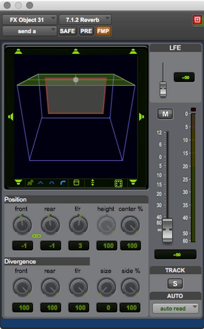
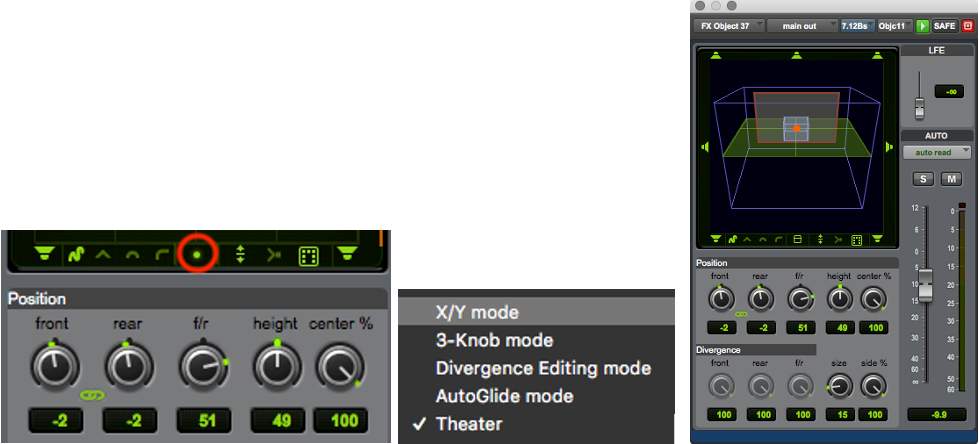
With the 7.0.2, 7.1.2, and Object panners, the Pro Tools Panning Mode selector provides access to the Theater option. When this mode is selected, the panner displays a 3D/Theater view.
Theater mode provides a 3D room view that can be rotated within the panner display.
To rotate the room view in Theater mode:
Move the cursor over the room view and use the scroll wheel to rotate the room up or down. Scroll all the way down for top-down view.
Parameter Indication in 3D/Theater Mode
Height, proximity, location, and screen position are all indicated in the Object panner when Theater mode is enabled.
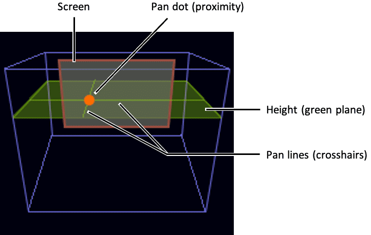
The display elements in the panner provide a visual indication of the signal in the three-dimensional space:
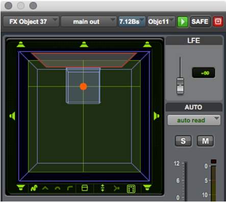
- Height — The Height plane represents the vertical elevation, as specified by the Height value in the panner.
- Proximity — The size of the pan dot indicates proximity relative to the current view. The pan dot appears smallest when panned furthest away and largest when panned nearest.
- Location — Pan lines appear on the Height plane to indicate Left/Right and Front/Rear location.
- Screen — The Screen image provides a visual reference for the front of the room in all views.
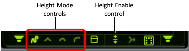
Height Mode
This series of controls in the panner sets the Height mode for the track. From left to right these choices are: FreeForm, Wedge, Sphere, and Ceiling modes.
FreeForm mode provides manual height adjustments; the others provide automatic height adjustment following their indicated shapes as the signal is panned front-to-rear or side-to-side. Changes to the Height mode can be automated.
To select the Height mode:
- Click a Height mode icon to activate that mode. The icon for the active mode will be highlighted in bright green.
To toggle the Height parameter on/off:
- Click the Height Enable icon. When lit, Height is enabled (requires FreeForm Height mode).
Height Knob
The Height knob becomes available when working in FreeForm mode with the Height function enabled/active. The Height parameter can be automated.
Adjusting Height in standard 2D view displays a vertical bar to the right of the pan grid to indicate the relative height of the track. In addition, the size of the pan dot increases as the Height value is increased.
In Theater mode, a green-colored Height plane shows the current Height value. The size of the pan dot indicates proximity.
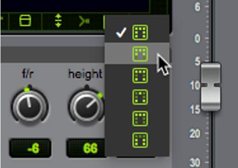
Zones Selector
The Zones selector sets the active speaker Zone (Zone Mask), which determines which speaker outputs are included as you pan a signal around the room.
Choices include All speakers, Front and side speakers (F/S), Front and rear speakers (F/R), Front-center and rear speakers (FC/R), Front speakers only, and Rear speakers only (including side speakers).
The speaker icons surrounding the panner grid appear as appropriate for the current Zone. The Zone Mask parameter can be automated, allowing you to automate changes to the current speaker Zone.
To change the Zone, do one of the following:
- Right-click the Zones selector and select the desired Zone from the menu.
- Click and hold on the Zones selector until the pop-up appears and select the desired Zone from the menu.
- Click the Zones selector to toggle through the available zones.
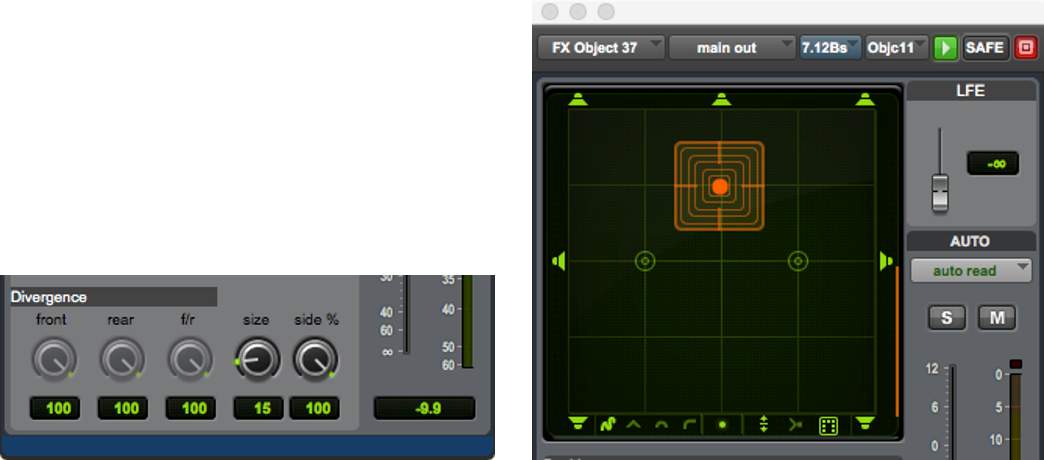
Size Knob
The Size knob can be used to increase or decrease the element size. When Size is set to any value above 0/off, a transparent grid (or cube if in 3D/Theater mode) surrounds the pan dot and the Divergence controls become inactive (grayed out).
The grid/cube around the pan dot gets larger as the Size value is increased and smaller as it is decreased. The Size value can be automated.
To change the element Size:
- Click and drag to adjust the Size knob, or hold down Shift and use the scroll wheel.
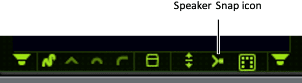
Speaker Snap
The Speaker Snap option in the panner allows you to toggle Dolby Atmos Speaker Snap on or off for tracks assigned to an Object. This option causes Object panning to move between discrete speakers in the Renderer, rather than creating a “phantom source” using a combination of multiple discrete speakers. With Speaker Snap enabled, the Renderer picks the nearest speaker to your panning coordinates and uses that to reproduce the sound object.
This may or may not be desirable, depending on the use case. If a point source sound is desired, this is a very useful control. However, if mixing in a 9.1.6 room configuration with Left and Right Wide speakers, for example, an object panned to the LW/RW speaker position with speaker snap enabled may either snap forward to the L/R screen channels, or back to the Lss/Rss, when rendered in a 7.1.4 or 5.1.4 configuration where the wide speakers are not present. Auditioning speaker snap using various speaker layouts is recommended to ensure the desired result is achieved.
The Speaker Snap setting can be automated.
To enable (or disable) Speaker Snap:
- Click the Speaker Snap icon to toggle it on/off.
Panning on Stereo Tracks
When the panner is used on stereo tracks, the default behavior is that the two panners are linked with Inverse Pan enabled so the pair are mirrored.
A Front/Rear Inverse can be enabled for greater flexibility.
Object/Bus Assignment and Automation Mode Indication
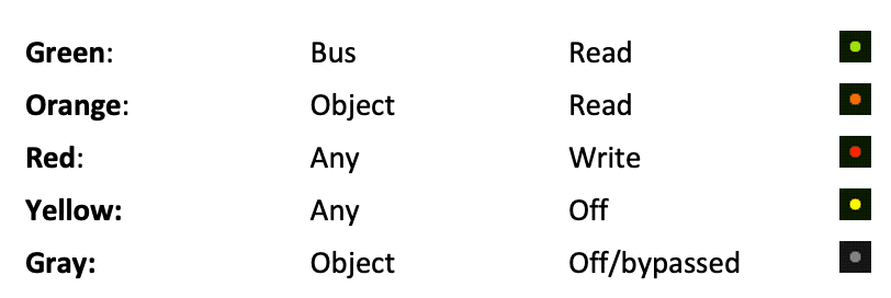
The Pan Dot in a track’s Output window, as well as in the graphic panner in I/O view (in both the Edit and Mix windows) changes color to indicate the track status. Various colors are used to indicate whether the track is in Bus or Object mode (as per the Bus/Object toggle), as well as whether the Track Automation mode is set to Read, any of the Write modes, or Off.
Play Video
Object Bypass
The Bypass function can be used to establish a workflow where multiple source tracks are assigned to the same Object, while only one of them is sending pan metadata to control the panning on the Renderer. This is an essential feature in sessions that have more tracks than available Object output paths to the Renderer.
To enable Object Bypass, do one of the following:
- bulletClick the Object Control Mode button in the Object view to cycle the Master Object Control mode to Bypass.
- bulletClick the Object Control Mode button in the Object panner to cycle the Master Object Control mode to Bypass.
The Object Control Mode button will display in gray when Bypass mode is active, as will the panner display area of the Object panner.
Note that this is not an automatable setting. When multiple tracks are allocated to the same object path, the Object Control Mode button becomes inactive on all bypassed tracks and cannot be altered while there is a track set to Master mode. All tracks will pass audio to the Renderer; however, the panner on the Master track must be used in order to provide panning metadata regardless of which track is providing the source audio.
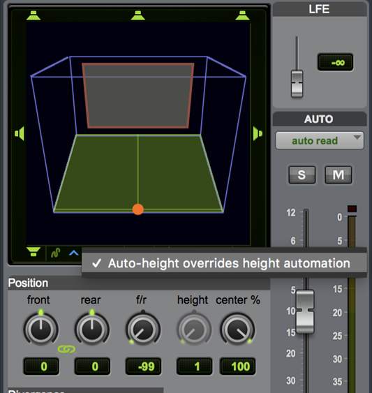
Auto-Height Overrides Height Automation Option
Pro Tools lets you re-purpose existing Front, Rear, and Front/Rear pan automation to automatically generate dynamic Height changes when mixing to Dolby Atmos (7.0.2 or 7.1.2). When this option is enabled, the selected Auto-Height mode overrides any Height automation, generating new height information automatically. This avoids having to write all new automation from scratch when opening existing 5.1 or 7.1 sessions and re-mixing them for Dolby Atmos (7.0.2 or 7.1.2 panning).
The Auto-Height Overrides Height Automation option is on by default if the track already has a main output assignment prior to assigning an Object output (assuming a re-use workflow). This option is off by default when translating automation from the Dolby Atmos Panner plug-in and also when a track has an Object output assigned but no main output assigned.
To commit automatically generated height data as automation, use the Coalesce Pan Guide Automation command. See “Coalesce Pan Guide Automation” below.
To enable (or disable) Auto-Height Overrides Height Automation:
- 11Open the Output window for the track you want.
- 2
- Double-click the Height Mode selector
- Right-click the Height Mode selector and select (or deselect) Auto-Height Overrides Height Automation
When exchanging current Pro Tools sessions that use Auto-Height Overrides Height Automation with older Dolby Atmos-compatible Pro Tools systems (Pro Tools HD 12.8 or 12.8.1), be sure to use Coalesce Pan Guide Automation first so that Height Pan Automation plays back correctly.
Coalesce Pan Guide Automation
To automatically generate Height automation using the selected Auto-Height mode:
- 11Select the tracks for which you want to generate Height automation.
- 22Choose Edit > Automation > Coalesce Pan Guide Automation.
The Dolby Atmos Music Panner
Lesson 4 of 6
The native Pro Tools panner can be used to create Dolby Atmos Music. Dolby also provides a dedicated Dolby Atmos Music Panner plug-in for use within Pro Tools and other DAWs.
The Dolby Atmos Music Panner plug-in has features that optimize it for mixing music. These include several unique panning patterns, unique mirror patterns on stereo tracks, and a sequencer for syncing object movement to the session tempo.
As the Dolby Atmos Music Panner is a plug-in, it writes plug-in automation distinct from panning automation; Dolby Atmos Music Panner automation is not written to the panning automation playlist in Pro Tools.
Communication with the Renderer and mapping to objects is controlled by the Dolby Atmos Music Panner plug-in directly and independently of the DAW.
Setting Up the Dolby Atmos Music Panner Plug-in
Before using the Dolby Atmos Music Panner plug-in in Pro Tools, be aware that the Dolby Atmos Music Panner cannot be used on an output that is currently mapped to an Object input in the I/O bus page.
It is possible to mix using the native Pro Tools panner on some tracks and the Dolby Atmos Music Panner on others. However, the Object mapping must be disabled so that the physical output is available to the bus in order to use the Music Panner.
If the session is to only use the Dolby Atmos Music Panner plug-in and not the native panner for objects, then communication with the Renderer only needs to be established to use the Renderer Input Configuration. For this workflow, do not map busses to objects in the Pro Tools I/O Setup Bus tab.
Introduction
To set up the Dolby Atmos Music Planner, follow the steps provided here.
Click the Start button to begin.START
Step 1
Insert the plug-in on a mono or stereo track.
Insert the Dolby Atmos Music Panner plug-in on a mono or stereo audio track (listed in the Soundfield drop-down list of plug-ins, when sorted by category).
1
2
3
4
5
6
7
8
9
Step 2
Enter the IP address or host name.

Enter the IP address/host name of the external Renderer, or localhost if the Renderer is running internally. The indicator will turn green when successfully connected.
1
2
3
4
5
6
7
8
9
Step 3
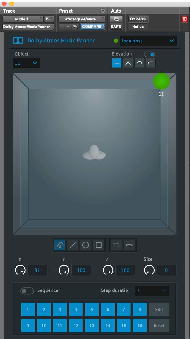
Select the Renderer Object (mono).
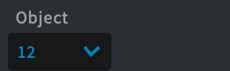
Select the Renderer Object for which the Dolby Atmos Music Panner is sending panning metadata to in the Object drop-down menu.
- Unavailable Object numbers will be grayed out.
1
2
3
4
5
6
7
8
9
Step 4
Select the Renderer Object (stereo).
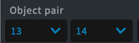
If inserted on a stereo track, the Object pairs are selected individually but should be set sequentially.
1
2
3
4
5
6
7
8
9
Step 5
Set the track output.
To ensure that audio and metadata are written to the same object, set the track output to the bus mapped to the same physical output. Note that the Object drop-down menu starts with Object 11, even if multiple beds are configured in the DAW I/O and Renderer input configuration. If the Bus names are offset, verify that the correct output is being used.
1
2
3
4
5
6
7
8
9
Step 6
Set the Bus/Object toggle to Bus.
If the Pro Tools session has the Edit Window View Object Column open, ensure the Bus/Object toggle is set to Bus.
1
2
3
4
5
6
7
8
9
Step 7
Enable global plug-in automation.
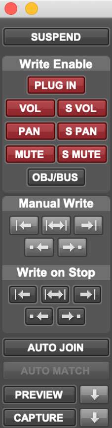
Enable global plug-in automation in Window > Automation.
1
2
3
4
5
6
7
8
9
Step 8
Enable plug-in parameters.
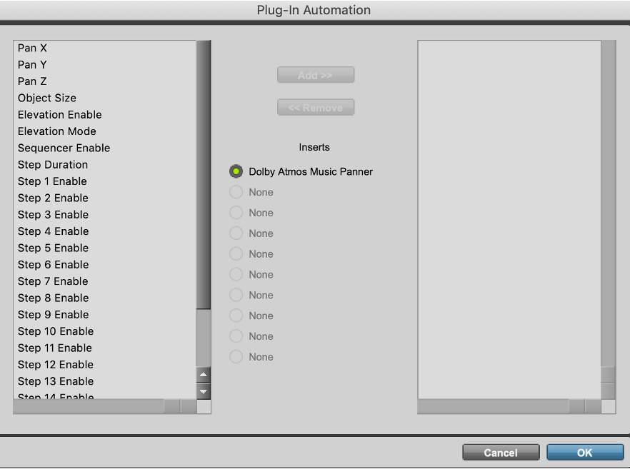
Enable the plug-in parameters from the Plug-in Automation window opened from the Dolby Atmos Music Panner.
First, select items on the left.
1
2
3
4
5
6
7
8
9
Step 9
Complete the set up.
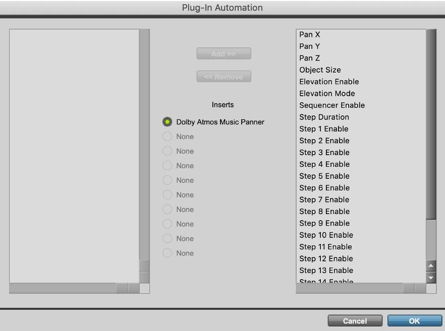
Click Add to move the items to the right column, then click OK to finish.
XYZ automation is written from the “puck”. XYZ automation is not written from the Sequencer paths described below. If needed, the XYZ automation from the step sequences can be written to the Pro Tools native panner by assigning the same track to the same Object in the Object view, with the Object Control Mode set to record. Once recorded, the Music Panner should be disabled. This is sometimes necessary if the audio moves within the session and winds up on a different bar of the tempo map.
1
2
3
4
5
6
7
8
9
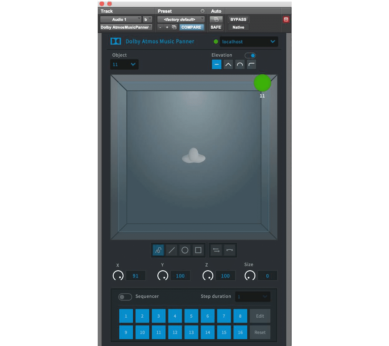
Using The Dolby Atmos Music Panner
The Dolby Atmos Music Panner plug-in’s basic functions are the same as the native Pro Tools panner:
- bulletThere is a height enable configured as an elevation toggle.
- bulletIt has the same height modes: FreeForm, Wedge, Dome, and Ceiling.
- bulletThe position functions are configured as X, Y, Z, and Size.
Differences from the native panner:
- bulletThere is only a single overhead view of a person in a virtual room.
- bulletSnap and Zone controls are not included.
Unique features of the Music Panner include:
- bulletA mono/stereo version that can be implemented on mono or stereo tracks.
- Mirror X – Mirrors X only
- Mirror Y – Mirrors Y only
- Mirror XY – Mirrors XY
- Copy – copies any action from one channel to the other
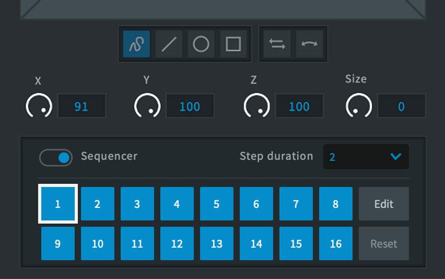
Sequencer Mode – The Dolby Atmos Music Panner includes a sequencer for creating up to 16 steps of dynamic Object panning.
Sequencer
The sequencer is engaged via the sequencer toggle at the bottom section of the Music Panner.
Once the sequence is enabled, any existing x, y, z settings created when the sequencer is off are ignored. Object size is retained.
Review the Sequencer usage information provided below in the zoomed in view, for creating and editing the sequence steps and paths. Click each popup to view the details before proceeding.
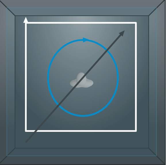
The color of the drawn paths in the virtual room indicated the status:
- bulletBlue: The object path is active and belongs to a step number block that is currently not editable.
- bulletWhite: The object path belongs to a step number block that is currently editable. The object path may be active or disabled.
- bulletGray: The object path is disabled because it belongs to a step number block that is disabled.
Additionally, the block is currently not editable.
The color of the drawn paths in the virtual room indicated the status:
- Blue: The object path is active and belongs to a step number block that is currently not editable.
- White: The object path belongs to a step number block that is currently editable. The object path may be active or disabled.
- Gray: The object path is disabled because it belongs to a step number block that is disabled.
Additionally, the block is currently not editable.
The Dolby Atmos Music Panner plug-in settings, including sequencer and movement paths can be saved as plug-in settings, greatly expanding the usability of the Music Panner.
Play Video
The Dolby Atmos Music Panner Template
The Dolby Atmos Music Panner plug-in installer has optional AAX, VST, and AU components and comes with a templates for Pro Tools, Ableton Live, Logic, and Nuendo. There is a companion .pio I/O setup that can be installed along with the Pro Tools template. The Pro Tools template has 64 outputs defined:
- bulletTen mono tracks for a 7.1.2 Bed. The native panner can be used for these, as Dolby Atmos Metadata is not required.
- bullet16 mono tracks with the Dolby Atmos Music Panner plug-in inserted.
- bullet16 stereo tracks with the Dolby Atmos Music Panner plug-in inserted.
Creating a Dolby Atmos Master File
Lesson 1 of 5
The Dolby Atmos Renderer can be used to record or export a Dolby Atmos master, or to write updated metadata to an existing master. A master can be recorded to (or punched in/out of) by using In and Out points, or by manually punching in and out in the Renderer.
Recording a Master
A Dolby Atmos mix is recorded to the Renderer in real-time as it plays back from Pro Tools. Prior to recording, it is important to verify the following settings for the Renderer and the Pro Tools session:
- bulletEnsure that the content starts after 00:00:00:00 on the Pro Tools timeline to allow for some pre-roll; master files cannot record across this point, and starting a recording at 0 hours without pre-roll will result in a short delay while the system syncs up and recording begins.
TIP: Five to ten seconds of pre-roll is suggested in order to ensure correct synchronization lock-up between Pro Tools and Renderer before recording
- bulletEnsure that the Renderer and the Pro Tools session have the same frame rate and sample rate. If mismatched, change the Renderer frame rate in Driver preferences, and make any changes required in your Pro Tools settings.
- bulletIt is recommended that re-render processing be disabled prior to recording. Live re-renders consume significant CPU resources and can potentially cause errors in a live recording.
To record a master using In and Out points:
Introduction
In this procedure, you will first create a new master file, and then initiate recording in Pro Tools. Click the Start button to begin.START
Step 1
Open the Create New Master File dialog box
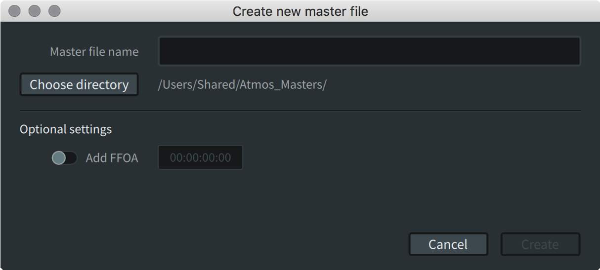
In the Renderer, choose File > New Master File or press Command+N (Mac) or Ctrl+N (Windows).
The Create New Master File dialog box will appear.
1
2
3
4
5
6
7
8
9
10
Step 2
Choose a name and directory for the file.

In the dialog box, provide a name and choose a directory location for the master file.
1
2
3
4
5
6
7
8
9
10
Step 3
Add a first frame of action (FFOA).
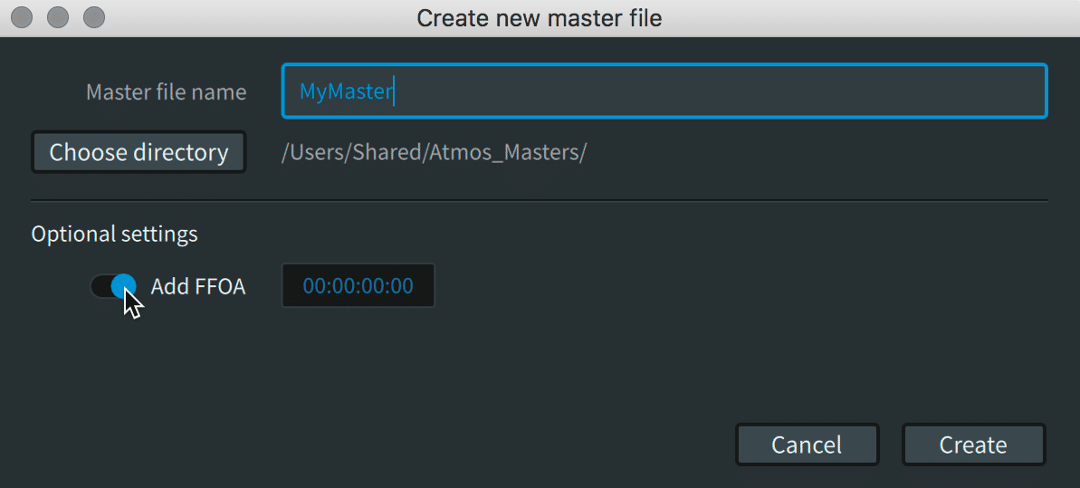
Though optional, a FFOA is best practice if the master file is to contain pre-roll (i.e., if the recording start/punch-in point is prior to the start of the content, which is often the case when not using In/Out points):
Click the Add FFOA switch to enable it.
1
2
3
4
5
6
7
8
9
10
Step 4
Enter a timecode value.

In the Add FFOA field, type in an FFOA timecode value (in hours:minutes:seconds:frames).
The FFOA time must be within the range of the new recording. If it is outside the range, it will not be written to the master file.
1
2
3
4
5
6
7
8
9
10
Step 5
Create the file.

Click Create. The Renderer is now ready for recording.
The file name will display in the top right of the Renderer window; however, the master file set will not be written to disk until the recording process has been completed.
1
2
3
4
5
6
7
8
9
10
Step 6
Synchronize to LTC

Enable the Sync On/Off button (clock icon) to put the Renderer into chase mode, synchronizing to LTC from Pro Tools.
1
2
3
4
5
6
7
8
9
10
Step 7
Set In and Out points
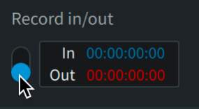
In the Record In/Out section, click the associated switch to move it to the down (enabled) position.
In the In field, set the timecode value where recording will start.
In the Out field, set the timecode value where recording will end.
1
2
3
4
5
6
7
8
9
10
Step 8
Enable the Record button

Click the Record button to enable it. The button will flash red if Record In/Out is enabled or light solid red if Record In/Out is disabled.
The Renderer will create the destination folder on the selected drive when the Record button is first engaged.
1
2
3
4
5
6
7
8
9
10
Step 9
Initiate the Renderer record pass.
Begin playback from Pro Tools to initiate the Renderer record pass.
Be sure to start playback at an appropriate location in the timeline, prior to the identified In point. Recording will not take place if playback begins after the active In point timecode. Five seconds of pre-roll is suggested in order to ensure correct synchronization lock-up between Pro Tools and Renderer before recording begins.
The record button will light solid when recording begins (or when playback reaches the In point) and will remain solid red until recording stops (or playback reaches the Out point).
1
2
3
4
5
6
7
8
9
10
Step 10
Stop the playback.
When the recording has completed (after the Out point), stop playback from Pro Tools.
If prompted with a message to add or update the FFOA, do so at this time, or click Cancel.
Note that the master file will always begin from the first In point recorded to disk, and that subsequent drop-ins must join with existing recorded audio. You cannot, for example, start recording at 01:30:00:00 and then go back to lay down audio from 01:00:00:00. Likewise, you cannot lay down a section of audio from 01:00:00:00 to 01:10:00:00, then skip ahead to lay down audio at 01:30:00:00 without first having recorded audio between 01:10:00:00 and 01:30:00:00.
1
2
3
4
5
6
7
8
9
10
Recording can be performed manually without the use of In and Out points. Begin playback in the DAW, and click the Record button to manually punch in and out of the Master file. Again, ensure there is sufficient pre-roll in the DAW to allow correct synchronization lock-up prior to punching in.
It is recommended to punch out in the Renderer prior to stopping playback in Pro Tools when recording manually to avoid possible audio gaps in the master.
Master File Set Results
The Renderer creates a master file set in the destination folder specified in the Create New Master File dialog box. This file set includes three separate files:
- bullet.atmos: This is the top-level file that provides essential information about the presentation contained in the master file set, in XML format.
- bullet.atmos.metadata: This file contains all of the 3D positional coordinates for object audio in the .audio file.
- bullet.atmos.audio: This file contains the audio data for all bed signals and objects. It is an interleaved PCM file stored in the Core Audio Format (CAF).
Opening and Playing a Dolby Atmos Master
Lesson 2 of 5
You can play back a Dolby Atmos master file in the native .atmos format or other supported master file formats using the Renderer.
Typically, an external synchronization source is used to start playback in conjunction with video playback. Alternatively, the Renderer’s transport controls can be used for audio-only playback.
The Renderer can open the following Dolby Atmos master file types for playback:
- bullet.atmos (or .damf)
- bulletADM BWF .wav
- bulletIMF IAB .mxf
- bulletCinema print master (.rpl)
- bulletDigital Cinema Package (DCP) IAB .mxf
- bulletpmstitch .xml
Playing an .mxf file
When playing back an .mxf file, a dialog prompts the entry of a Start time. The default starts playback at frame 1 (timecode 00:00:00:00).
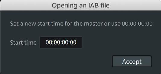
Playing Back a Master File Without Synchronization
This workflow does not require Pro Tools to be open.
Step 1
Open the master file.
- In the Renderer, choose File > Open Master File, or press Command+O (Mac) or Ctrl+O (Windows).
- Locate the Dolby Atmos media file and open it.
1
2
3
4
5
6
Step 2
View the opened file information.
The Renderer updates and provides information about the master in the top right of the Renderer window:
- File path and name
- Locked status
- Frame rate (timecode rate)
- FFOA (if any)
- Start and end times
The Source Input/Master button automatically enables (if it was previously disabled).
1
2
3
4
5
6
Step 3
Enable the Master button.
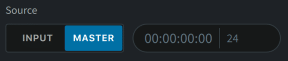
In the Source section, ensure that the Master button is enabled. With a master open and the Renderer in Master mode, you can play back and listen to the master file.
1
2
3
4
5
6
Step 4
Enter the beginning timecode.
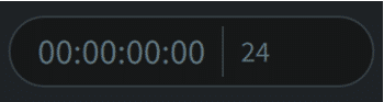
In the timecode readout, enter the timecode for the location where you want playback to begin. By default, the timecode readout location is the start of the currently loaded master file.
1
2
3
4
5
6
Step 5
Disable the synchronization button before playback.

In the Renderer transport section, disable the synchronization button and click the Play button to start playback.
1
2
3
4
5
6
Step 6
Stop the playback.

When done, stop playback by doing one of the following:
- Click the Stop button to stop playback and return the timecode location to the start of the loaded master file.
- Press the Spacebar or click the Play button to stop playback at the current location.
1
2
3
4
5
6
Playing Back a Master File With Synchronization to LTC
Step 1
Open the master file.
- In the Renderer, choose File > Open Master File, or press Command+O (Mac) or Ctrl+O (Windows).
- Locate the Dolby Atmos media file and open it.
1
2
3
4
5
6
7
Step 2
View the opened file information.
The Renderer updates and provides information about the master in the top right of the Renderer window:
- File path and name
- Locked status
- Frame rate (timecode rate, in fps)
- FFOA (if any)
- Start and end times
Exporting Additional Dolby Atmos Master File Formats
Lesson 3 of 5
A Dolby Atmos project will typically require delivery in one or more Dolby Atmos master file master file formats.
Master file formats include the following:
- bullet.atmos file set, comprised of .atmos, .atmos.audio, and .atmos.metadata files
- bulletADM BWF, a .wav file
- bulletIMF IAB, an .mxf file
Note that IMF IAB is considered a mezzanine rather than a master format. While the audio is uncompressed, the panning automation is quantized with IMF IAB.
ADM BWF and IMF IAB files can be exported from an open Atmos master file. An .atmos master file cannot be exported from an open ADM BWF or an IMF IAB.
The .atmos package can be created only as part of a new master recording in the Dolby Atmos Renderer, or by using the Dolby Atmos Conversion Tool. The Dolby Atmos Conversion Tool can be used to create an .atmos file set from ADM BWF, IMF IAB, and other Dolby Atmos Theatrical master file formats.
Both the ADM BWF and IMF IAB export windows allow for export of the entire master, or for export of a user-specified range. This is particularly useful to trim off a slate, synchronization 2-pops, or any unnecessary post-roll when exporting Master Files to be used as encoding masters.
Only 48 kHz masters can be used for export operations. 96 kHz masters can be converted to 48 kHz and other formats using the Dolby Atmos Conversion Tool.
Exporting an ADM BWF File
Use the following procedure to export an ADM BWF from a loaded master file.
Step 1
Open the Export Master to ADM BWF .wav dialog box

Choose File > Export Audio > ADM BWF, or press Command+A (Mac) or Ctrl+A (Windows).
The Export Master to ADM BWF .wav dialog box will display.
1
2
3
4
5
6
Step 2
Choose a directory destination.
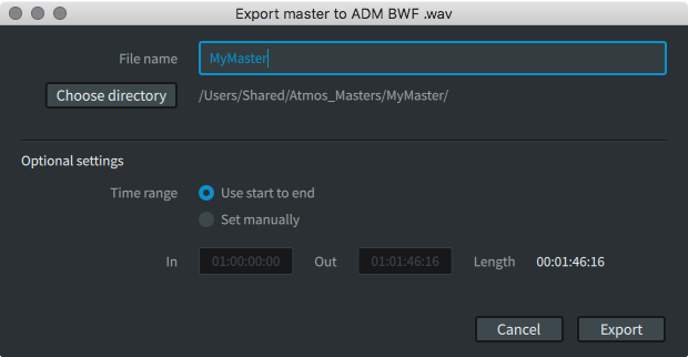
Click the Choose Directory button, and select a save location for the ADM BWF master.
1
2
3
4
5
6
Step 3
Name the file.

In the File name field, type a name for the ADM BWF file.
1
2
3
4
5
6
Step 4
(Optional) Set a time range.
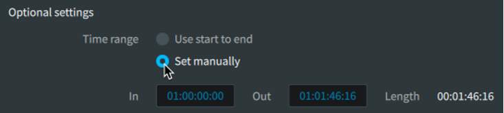
(Optional) In the Optional settings section, set the time range for the file:
- Click (enable) the Set manually radio button.
- In the In field, type in the timecode value where the file should start.
- In the Out field, type in the timecode value where the file should end.
1
2
3
4
5
6
Step 5
Export the file.

Click Export. A window will appear, showing the status of the export.
1
2
3
4
5
6
Step 6
Complete the export.
When the export has completed (100%), click the Close button to dismiss the window.
The new ADM BWF .wav file will now be available at the specified destination.
1
2
3
4
5
6
Exporting an IMF IAB File
When configuring the IMF IAB for export, a primary language must be set. This is required as part of the IMF specification.
Use the following procedure to export an an IMF IAB from an open master file.
Step 1
Open the Export Master to ADM BWF .wav dialog box
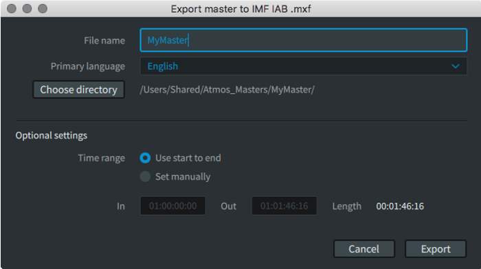
Choose File > Export Audio > IMF IAB, or press Command+A (Mac) or Ctrl+A (Windows).
The Export Master to IMF IAB .mxf dialog box will appear.
1
2
3
4
5
6
7
Step 2
Choose a directory destination.

In the Export Master to IMF IAB .mxf dialog box, click the Choose directory button, and set a path for the IMF IAB master file.
1
2
3
4
5
6
7
Step 3
Name the file.

In the File name field, type a name for the IMF IAB file.
1
2
3
4
5
6
7
Step 4
Select a primary language.
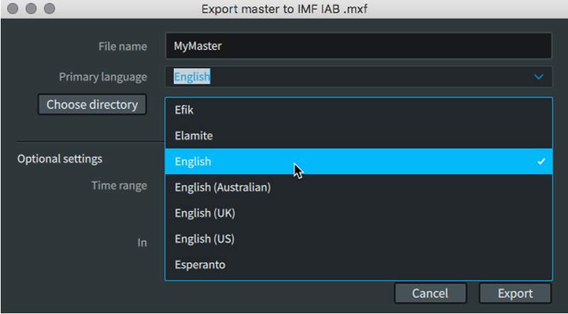
Do one of the following to select a primary language:
- Click the Primary Language pop-up menu and select the desired language.
- Click in the Primary Language field, and type the first letters to scroll to the desired language, and then select it.
1
2
3
4
5
6
7
Step 5
(Optional) Set a time range.
(Optional) In the Optional settings section, set the time range for the file:
- Click (enable) the Set manually radio button.
- In the In field, type in the timecode value where the file should start.
- In the Out field, type in the timecode value where the file should end.
1
2
3
4
5
6
7
Step 6
Export the file.

Click Export. Click Export. A window will appear, showing the status of the export.
1
2
3
4
5
6
7
Step 7
Complete the export.
When the export has completed (100%), click the Close button to dismiss the window.
The new IMF IAB .mxf file will now be available at the specified destination.
The start time of an IMF IAB .mxf will default to zero. A custom start time can be defined when opening the file. This information is not written to the file, but it will be used as a reference within the Renderer until the master is closed.
1
2
3
4
5
6
7
The In and Out points adjust to the frame boundaries at the start and end of the file if the master does not start and end on a frame boundary. This happens whether you manually set the In and Out points for the export or use the inherited start-to-end values of the input file.
Master file exports performed using the Renderer Remote application will only allow export to the external workstation. Only the local drives on the external workstation will be available for export. Network attached storage will not be available and should not be used.
